Download
1 / 22
220 likes | 242 Views
This lecture covers state encoding and partitioning strategies in digital systems, including one-hot encoding, output encoding, and hybrid approaches. Examples and techniques for minimizing logic are discussed.

E N D
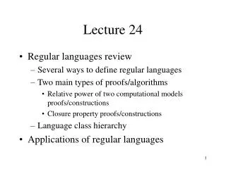
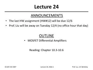
Lecture 24 • Logistics • HW7 back today • Midterm2 back today (Average 80/100) • Solution on-line this PM • HW8 due Wednesday • Ant extra credit due Friday • Final exam, Wednesday March 18, 2:30-4:20 pm here • Review session Monday, March 16, 4:30 pm, here • Last lecture • State encoding • One-hot encoding • Output encoding • State partitioning • Today • Encoding & Partitioning examples
State-encoding strategies • No guarantee of optimality • An intractable problem • Most common strategies • Binary (sequential) – number states as in the state table • Random – computer tries random encodings • Heuristic – rules of thumb that seem to work well • e.g. Gray-code – try to give adjacent states (states with an arc between them) codes that differ in only one bit position • One-hot – use as many state bits as there are states • Output – use outputs to help encode states • Hybrid – mix of a few different ones (e.g. One-hot + heuristic)
One-hot encoding • One-hot: Encode n states using n flip-flops • Assign a single “1” for each state • Example: 0001, 0010, 0100, 1000 • Propagate a single “1” from one flip-flop to the next • All other flip-flop outputs are “0” • The inverse: One-cold encoding • Assign a single “0” for each state • Example: 1110, 1101, 1011, 0111 • Propagate a single “0” from one flip-flop to the next • All other flip-flop outputs are “1” • “almost one-hot” encoding (modified one-hot encoding) • Use no-hot (000…0) for the initial (reset state) • Assumes you never revisit the reset state till reset again.
new value reset clock open/closed Another Encoding Example: Digital combination lock • An output-encoded FSM • Punch in 3 values in sequence and the door opens • If there is an error the lock must be reset • After the door opens the lock must be reset • Inputs: sequence of number values, reset • Outputs: door open/close
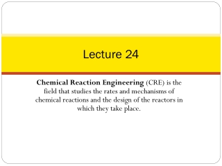
Design datapath first After the state diagram Before the state encoding Control has 2 outputs Mux control to datapath Lock open/closed new reset C1 C2 C3 4 4 4 mux control multiplexer 4 controller clock value comparator equal 4 open/closed Separate data path and control
ERR closed not equal& new not equal& new not equal& new S0 S1 S2 S3 closed mux=C1 closed mux=C2 closed mux=C3 start open equal& new equal& new equal& new not new not new not new Draw the state diagram
valuei C1i C2i C3i mux control C1 C2 C3 4 4 4 mux control multiplexer 4 value comparator equal 4 equal Design the datapath • Choose simple control • 3-wire mux for datapath • Control is 001, 010, 100 • Open/closed bit for lock state • Control is 0/1
Output encode the FSM • FSM outputs • Mux control is 100, 010, 001 • Lock control is 0/1 • State are: S0, S1, S2, S3, or ERR • Can use 3, 4, or 5 bits to encode • Have 4 outputs, so choose 4 bits • Encode mux control and lock control in state bits • Lock control is first bit, mux control is last 3 bits S0 = 0001 (lock closed, mux first code) S1 = 0010 (lock closed, mux second code) S2 = 0100 (lock closed, mux third code) S3 = 1000 (lock open) ERR = 0000 (error, lock closed)
FSM has 4 state bits and 2 inputs... • Output encoded! • Outputs and state bits are the same • How do we minimize the logic? • FSM has 4 state bits and 2 inputs (equal, new) • 6-variable K-map for all five states? • Way too complicated • Notice the state assignment is close to one-hot • ERR state (0000) is only deviation • Is there a clever design we can use?
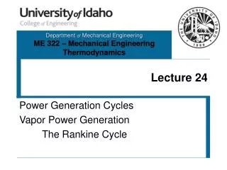
ERR closed not equal& new not equal& new not equal& new S0 S1 S2 S3 closed mux=C1 closed mux=C2 closed mux=C3 start open equal& new equal& new equal& new not new not new not new Encode 4 state bits A clever way for ERR is to use both Preset/Clear in existing flipflops. Not equal & new Preset0 = start Preset1,2,3 = 0 Reset0 = start’(E’N + (Q0+Q1+Q2+Q3)’) Reset1,2,3 = start + (E’N + (Q0+Q1+Q2+Q3)’) S0+ = S0N’ S1+ = S0EN + S1N’ S2+= S1EN + S2N’ S3+ = S2EN + S3 Already in ERR
S0 S0 D0 = Q0N’ D1 = Q0EN + Q1N’ D2= Q1EN + Q2N’ D3 = Q2EN + Q3 S0 E N S1 N’ S1 Preset0 = start Preset1,2,3 = 0 Reset0 = start’(E’N + (Q0+Q1+Q2+Q3)’) Reset1,2,3 = start + (E’N + (Q0+Q1+Q2+Q3)’) S1 E N S2 N’ S2 S0 S1 S2 S3 S2 E N S3
Add idles states to handoff control between machines State Partitioning C1 S1 S6 C2 C3 S2 S5 S3 S4 C4 C5 S1 S6 C1 C1•S1 (C2•S6)’ C2•S6 C2 (C1•S1+C3•S2+ C4•S3+ C5•S2)’ S2 SA S5 C3•S2+C4•S3 SB C3+C5 S3 S4 C4 C5•S2
Example: Traffic light controller • Highway/farm road intersection farm road car sensors highway
Example: traffic light controller • A busy highway is intersected by a little used farm road • Detectors C sense the presence of cars waiting on the farm road • with no car on farm road, lights remain Green in highway direction • if vehicle on farm road, highway lights go from Green to Yellow to Red, allowing the farm road lights to become Green • these stay Green only as long as a farm road car is detected but never longer than a set interval • when these are met, farm lights transition from Green to Yellow to Red, allowing highway to return to Green • even if farm road vehicles are waiting, highway gets at least a set interval as Green
ST Traffic Light Controller Interval Timer short long TS TL Example: traffic light controller • Assume you have an interval timer that in response to a set (ST) signal generates both: • a short time pulse (TS) and • a long time pulse (TL) • TS is to be used for timing yellow lights and TL for green lights ST TS TL
Example: traffic light controller • InputsDescription reset place FSM in initial state C detect vehicle on the farm road TS short time interval expired TL long time interval expired • OutputsDescriptionHG, HY, HR assert green/yellow/red highway lights FG, FY, FR assert green/yellow/red farm road lightsST start timing a short or long interval • States – some light configurations imply othersStateDescriptionHG highway green (farm road red)HY highway yellow (farm road red)FG farm road green (highway red)FY farm road yellow (highway red)
Example: traffic light controller reset C HG HY HR ST Traffic Light Controller Interval Timer TS TL FG FY FR
Example: traffic light controller • State diagram Outputs not shown: FR=HG+HY HR=FG+FY Reset (TL•C)' HG TL•C / ST TS / ST HY FY TS' TS' TS / ST TL+C' / ST FG (TL+C')'
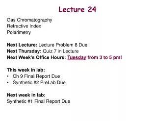
Reset (TL•C)' HG TL•C / ST TS / ST HY FY TS' TS' TS / ST TL+C' / ST FG (TL+C')' Example: State Partitioning
(TL•C)' HG TS•FY TL•C / ST Reset TS / ST HR FR TS / ST HY TS' TS•HY State partitioning for traffic light controller Reset Add idle states Add return arcs Label idle wait loops (TS•HY)’ FY TS' (TS•FY)’ TL+C' / ST FG (TL+C')'
Minimize communication between partitions • Ideal world: Two machines handoff control • Separate I/O, states, etc. • Real world: Minimize handoffs and common I/O • Minimize number of state bits that cross boundary • Merge common outputs • Look for: • Disjoint inputs used in different regions of state diagram • Outputs active in only one region of state diagram • Isomorphic portions of state diagram • Add states, if necessary, to make them so • Regions of diagram with a single entry and single exit point
FSM design: A multi-step process 1. Understand the problem – State diagram and state-transition table 2. Determine the machine’s states – Consider missing transitions: Will the machine start? – Minimize the state diagram: Reuse states where possible 3. Encode the states – Encode states, outputs with a reasonable encoding choice – Consider the implementation target 4. Design the next-state logic – Minimize the combinational logic – Choices made in steps 2 & 3 affect the logic complexity 5. Implement the FSM