Download

1 / 43
430 likes | 522 Views
HEIGHTS Integrated Models for Liquid Walls in IFE. A. Hassanein and HEIGHTS Team. Presented at the ARIES Meeting April 22-23, 2002, Madison, WI. Argonne National Laboratory. Outline. Hydrodynamics of Gas-Filled Chamber Atomic Physics of Chamber Gases Radiation Transport in Gas/Vapor

E N D
HEIGHTS Integrated Models for Liquid Walls in IFE A. Hassanein and HEIGHTS Team Presented at the ARIES Meeting April 22-23, 2002, Madison, WI Argonne National Laboratory
Outline • Hydrodynamics of Gas-Filled Chamber • Atomic Physics of Chamber Gases • Radiation Transport in Gas/Vapor • Response of Thin Liquid Films • Behavior of Thick Liquid Walls • Aerosol Formation
Hydrodynamic Methods • Conservative system of hydrodynamic equations in matrix form for 1-D spherical case: • Table of thermodynamic properties (CRE calculated) is used for this case. • Total Variation Diminishing (TVD) scheme ensures stable numerical calculations and that the total variation does not increase with time:
Calculation Methods • In Lax-Friedrich formulation TVD-correction components are calculated from maximum propagation speed: • Hancock predictor step achieves second order temporal accuracy: where are limited differences.
Calculation Methods • By using TVD method we ensure no generation of non-physical oscillations along shock waves. • Mechanisms of numerical (mathematical) dissipation with control automatic feedback allow transformation of shock wave kinetic energy into heat energy in this case. • Artificial viscosity and other adjusting parameters are not used. • TVD can solve shock-wave problem within 2-4 cells only. • Test calculations of standard cases show that TVD results are much closer to experimental data compared to "artificial viscosity" methods.
Hydrodynamic Phenomena • Two cases of shock wave propagation in the chamber are studied: • rarefied gas; • dense gas.
Hydrodynamic Phenomena Pressure of shock-wave evolution in case of rarefied (left) and dense (right) Xe Heated gas area forms in front of the dense wave as result of absorbed radiation. Pressure increases in this region and the "classical" wave-shape is distorted.
HEIGHTS ATOMIC MODELS Hartree-Fock- Slater for Calculation of Atomic Data CRE model for Calculation of opacities and Equation-of-state Self-consistent model includes radiation excitation Auger model No radiation di-electronic transition Non stationary Model includes Auger and self- consistent. Splitting of levels and lines for high-Z materials
CRE MODEL • Collisional ionization and three particle recombination • Collisional excitation and de-excitation • Spontaneous transition in lines • Photo-recombination • Di-electronic recombination
CRE MODEL • Collisional excitation (de-excitation) and ionization (three body recombination): Born or Born-Coloumb approximation • Photo-recombination: using wave functions from HF or HFS calculation • Spontaneous transition probabilities: using wave functions from HF or HFS calculation • Di-electronic recombination
Self-Consistent Model • Same processes of CRE model • Photo-ionization • Photo-excitation in lines • Solution kinetic and radiation transfer equation
Auger Model • The processes of self-consistent model • X- ray produced vacancy in inner shells • Non radiation Coster-Cronig and Auger processes • Characteristics line transitions in vacancy • New Auger processes (cascades)
Non-Stationary Model • Characteristic hydrodynamic time is comparable with atomic transition time • It is necessary to solve system of non stationary kinetic equations • Non stationary kinetic model • Quasi-stationary kinetic model
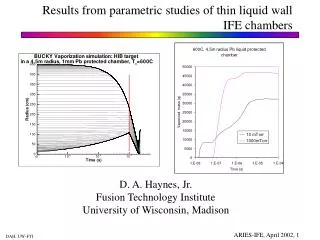
Surface Temperature No gas 0.05 torr Xe 0.5 torr Xe
Radiation Transfer • 1-D spherical forward-reverse method • 1-D cylindrical forward-reverse method • 2-D cylindrical forward-reverse method • 2-D cylindrical SN method
ENHANCED CRE MODEL for HIGH-Z MATERIALS • Relativistic effects are taken into account for calculation of both level structure and transition probabilities for high-Z materials. • Collisional and radiation transition not only from ground and excited states, but also transitions from inner shells are very important.
LEAD ATOMIC STRUCTURE • In our calculations for lead we took into account 495 separate lines from 50 ions with detail resolution of lines profiles. • About 70% of all lines are from inner shells.
PhotonSpectra HI ID, 458 MJ High-Yield DD, 401 MJ NRL DD, 154 MJ
Surface TemperatureHigh-Yield Direct Drive Target, 401 MJ Lead Lithium
Surface TemperatureDirect Drive Target, Lead Wall High Yield Low Yield
Temperature Rise in Lead WallLaser, X-ray, and ion depositions, Direct Target
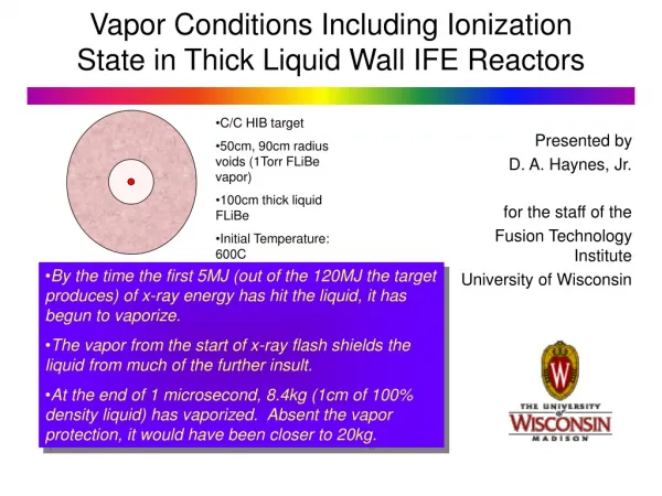
Behavior of Thick Liquids • Neutron energy deposition in thick liquid jets will result in temperature • and thermal pressure rise. • Instant rise of pressure results in excitation of sound waves mainly in • radial direction. During these excitations, pressure oscillates with • magnitude ± P. • Liquid metals subjected to negative pressure are metastable. • Spontaneous formation of cavities in stressed liquid can result in • fragmentation. • Fracture pressure of liquid metals depends on their purity. Previous • experimental results are in good agreement with Fisher’s theory. • After neutron energy deposition and depending on target yield liquid • negative tension reaches –10 to -20 katm which exceeds the fracture • pressure.
Aerosol Formation • Intense heating allows bubbles to grow, reache liquid surface, and then bursts. • Because of surface tension liquid flows around exploded bubble and forms jet • shooting to top. The jet is then splits into droplets due to also surface tension • instability. • with increment • Jet is divided into droplets with size Rk proportional to growth time when wave • amplitude achieves jet radius, i.e., distribution of droplets Nk(k) is
Macroscopic Droplet Formation • Distribution droplets in one bubble with radius Rb can be obtained from mass • conservation law • and distribution of droplets is • By averaging on Rb one can obtain distribution of all droplets in a layer with • depth h where Rmin is function of surface tension and pressure inside bubble. • Therefore, total droplets distribution is given by