Download
1 / 27
280 likes | 511 Views
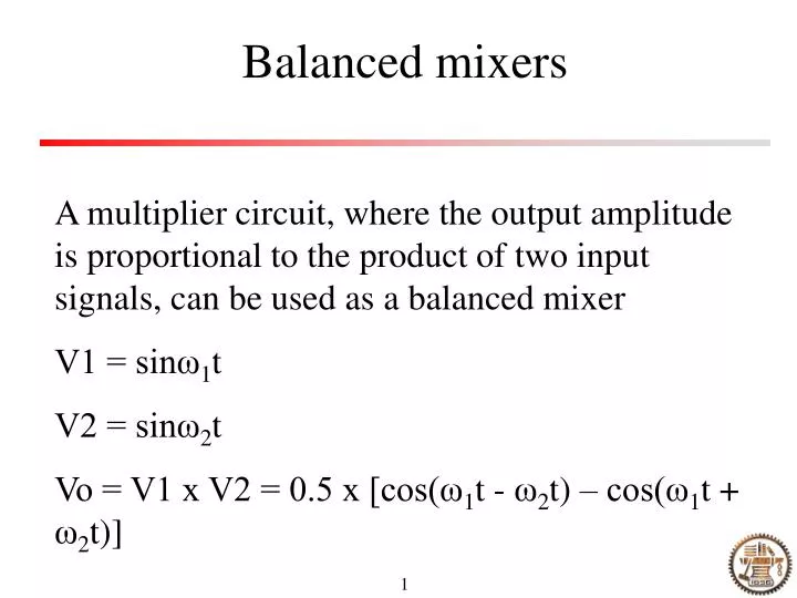
Balanced mixers. A multiplier circuit, where the output amplitude is proportional to the product of two input signals, can be used as a balanced mixer V1 = sinω 1 t V2 = sinω 2 t Vo = V1 x V2 = 0.5 x [cos(ω 1 t - ω 2 t) – cos(ω 1 t + ω 2 t)]. Applications of balanced mixers.

E N D
Balanced mixers A multiplier circuit, where the output amplitude is proportional to the product of two input signals, can be used as a balanced mixer V1 = sinω1t V2 = sinω2t Vo = V1 x V2 = 0.5 x [cos(ω1t - ω2t) – cos(ω1t + ω2t)]
Applications of balanced mixers Data (…01101001…) AM Modulation Output Signal Carrier Signal input Output Signal AM de-modulation Filter Local oscillator
Detection schemes Homodyne and heterodyne detection One example of heterodyne detection (See P. Hu’s paper) Self-mixing homodyne detection Signal input Output Signal Filter
Phase detector using mixer Signal input The DC output depends on the phase of the two paths The output is related to the phase difference of the two signals of the same frequency
Comparison of oscillators LC oscillators: susceptible to vibration, temperature changes, aging… Crystal oscillators: Good stability, but narrow tuning range Frequency synthesizers: Good stability and tunability, preferred method of frequency generation in most modern transmitters and receivers
Central component of frequency synthesizer - phase locked loop Phase detector LPF Amp VCO Output Input The output always tracks the input frequency Besides frequency tracking, one immediate application is clock recovery
How to characterize a PLL Capture range: The range over which the reference frequency can be varied and still achieve phase lock Lock range: The total frequency range within which lock, once achieved, can be maintained Example 2.8
Simple frequency synthesizer Phase detector LPF Amp VCO Output Input / N divider FM and AM channel spacing Example 2.9
A practical example – 29M to 4.8M synchronization circuit 29MHz / 6 circuit 29MHz amplification, digitization and frequency division circuit (All capacitors are 0.1uF).
Experimental results Spectrum of 4.827MHz square signal wave. Span: 500Hz, RB: 30Hz. Spectrum of 4.827MHz square signal wave. Span: 500Hz, RB: 30Hz.
Pre-scaling Phase detector LPF Amp VCO Output Input Fixed /Q Fixed /M Programmable /N Example 2.10
Frequency translation The movement of a block of frequencies is called a frequency translation Two configurations: Synthesizer with frequency shifting Synthesizer with mixer in the loop Example 2.11
Transmission lines Coaxial cables (solid dielectric, air dielectric) Parallel line cables (television twin-lead, open-wire line, shielded twin-lead) Twisted pair cable – used as transmission lines for relatively low frequencies
Two models of short transmission line section Balanced line R L G C Unbalanced line At DC, the inductance and the capacitor have no effect
Step and pulse response of lines Transmission line Vi Since the line has capacitance to be charged, the initial current will not be zero
Characteristic impedance Characteristic impedance: the ratio of voltage to current through the transmission line with a step signal Concept of matched line Characteristic impedance Z0 = sqrt[(R + jwL) / (G + jwC)] Many lines approach Z0 = sqrt(L/C) Example 14.1, 14.2
Reflection (step input) Open end scenario Short end scenario Energy does not disappear at the open end, since there is nothing capable of dissipating energy Pulse input…
Some definitions • Γ = Vr/Vi: reflection efficient • Γ = (ZL – Z0) / (ZL + Z0) • Meaning of the above equation: • To have zero reflection, ZL has to be equal to Z0 • By measuring Γ, ZL can be derived to probe the internal characteristic of the load • Example 14.13
An example to know the internal parameters of a tunable laser Transmission line Source S11 Parameters Reflector biased at 10 mA Is (A) 1.79E10-5 q 4.47 Rp (ohm) 0.1 Rs (ohm) 0.1 Rsub (ohm) 1.0 Cp (pF) 4.58 Cs (pF) 355 Lp (nH) 21.4 S11 = (ZL – Z0) / (ZL + Z0)
Voltage driver is better than current driver Y. Su et al, IEEE PTL Sept. 2004 Current response Optical response
Wave propagation In a matched line, a sine wave moves down the line and disappear into the load. Such a signal is called a traveling wave Example 14.5 RF Phase shifter
Standing waves The interaction between the incident and reflected waves causes what appears to be a stationary pattern of waves on the line, which are called standing waves SWR = Vmax/Vmin For a matched line, the SWR = 1
Relation between Γ and SWR SWR = (1+ |Γ|) / ( 1 - |Γ|) If ZL >Z0, SWR = Z0 / ZL Example 14.6