Download
1 / 36
370 likes | 693 Views
MT411 Robotic Engineering. Chapter 4 Forward Kinematics. Asian Institution of Technology (AIT). Narong Aphiratsakun, D.Eng. Forward Kinematics. Kinematics is a description on motion of the manipulator without consideration of the forces and torques which cause the motion.

E N D
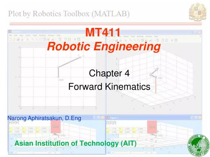
MT411Robotic Engineering Chapter 4 Forward Kinematics Asian Institution of Technology (AIT) Narong Aphiratsakun, D.Eng
Forward Kinematics Kinematics is a description on motion of the manipulator without consideration of the forces and torques which cause the motion. Forward kinematic is to determine the position and orientation of the end effector given the values for the joint variables of the manipulator.
Kinematics Chains Robot manipulator is composed of a set of links connected by joints. A robot manipulator with n joints will have n+1 links. Joint is number from 1 to n. Links is number from 0 to n (0 is base). Therefore joint i connects link i-1 to link i. When joint i is actuated, link i moves, link 0 is fixed.
2 Links manipulator Determine the position and orientation of the end effector in term of joint variables.
2 Links manipulator [ cos(theta1)*cos(theta2) - sin(theta1)*sin(theta2), - cos(theta1)*sin(theta2) - cos(theta2)*sin(theta1), 0, L2*(cos(theta1)*cos(theta2) - sin(theta1)*sin(theta2)) + L1*cos(theta1) ; cos(theta1)*sin(theta2) + cos(theta2)*sin(theta1), cos(theta1)*cos(theta2) - sin(theta1)*sin(theta2), 0, L2*(cos(theta1)*sin(theta2) + cos(theta2)*sin(theta1)) + L1*sin(theta1) ; 0, 0, 1, 0; 0, 0, 0, 1]
The Denavit-Hartenberg (DH) Convention It is possible to carry out forward kinematics analysis as we did for 2 links manipulator. However, the kinematic analysis of an n-link manipulator can be extremely complex and the Denavit-Hartenberg (DH) simplify the analysis. This DH is a universal language with which engineer can communicate. • ai : link length • i : link twist • di : link offset (prismatic joint) • i : joint angle (revolute joint) **Assign zi to be the axis of actuation for joint i+1.
The Denavit-Hartenberg (DH) Convention DH1: the axis x1 is perpendicular to the axis z0. DH2: the axis x1 intersects the axis z0.
The Denavit-Hartenberg (DH) Convention DH1: the axis x1 is perpendicular to the axis z0. DH2: the axis x1 intersects the axis z0.
The Denavit-Hartenberg (DH) Convention DH1: the axis x1 is perpendicular to the axis z0. DH2: the axis x1 intersects the axis z0.
The Denavit-Hartenberg (DH) Convention • ai : distance between axes zi and zi+1, and measured along the axis xi. • i : angle between axes zi and zi+1, and measured in a plane normal to xi. • di : distance from origin to the intersection of the axis xi+1 with zi, and measured along the axis zi. • i : angle from xi to xi+1, and measured in a plane normal to zi.
The Denavit-Hartenberg (DH) Convention • a: distance between axes z0 and z1, and measured along the axis x1. • : angle between axes z0 and z1, and measured in a plane normal to x1. • d : distance from origin O0 to the intersection of the axis x1 with z0, and measured along the axis z0. • : angle from x0 to x1, and measured in a plane normal to z0.
DH Examples : 2 links manipulator link1 • a1 (distance between axes z0 and z1, and measured along the axis x1) : a1 • 1 (angle between axes z0 and z1, and measured in a plane normal to x1) : 0 • d1 (distance from origin O0 to the intersection of the axis x1 with z0, and measured along the axis z0) : 0 • 1 (angle from x0 to x1, and measured in a plane normal to z0) : 1* link2 • a2 (distance between axes z1 and z2, and measured along the axis x2) : a2 • 2 (angle between axes z1 and z2, and measured in a plane normal to x2) : 0 • d2 (distance from origin O1 to the intersection of the axis x2 with z1, and measured along the axis z1) : 0 • 2 (angle from x1 to x2, and measured in a plane normal to z1) : 2*
DH Examples : 2 links manipulator (MATLAB) Manipulate by MATLAB with DH formula T02 = [ cos(theta1)*cos(theta2) - sin(theta1)*sin(theta2), - cos(theta1)*sin(theta2) - cos(theta2)*sin(theta1), 0, L1*cos(theta1) + L2*cos(theta1)*cos(theta2) - L2*sin(theta1)*sin(theta2) ; cos(theta1)*sin(theta2) + cos(theta2)*sin(theta1), cos(theta1)*cos(theta2) - sin(theta1)*sin(theta2), 0, L1*sin(theta1) + L2*cos(theta1)*sin(theta2) + L2*cos(theta2)*sin(theta1) ; 0, 0, 1, 0 ; 0, 0, 0, 1 ]
DH Examples : 2 links manipulator (Robotics Toolbox) Manipulate by MATLAB with DH formula by Robotics Toolbox
Assignment: 1 Q1. With the given reference [x0, y0, z0] and P0 = [0, 0, 0], obtain the transformation matrix (T) for following cases. Note: You should draw all the frames when rotating and translating is performed. a). 1: rotate in z-axis by 90, 2: translate in y-axis by 2 unit, and 3: rotate in x-axis by -90. Draw final frame compare with reference frame when transformation is performed. b). 1: rotate in y-axis by -90, 2: translate in y-axis by -2 unit, and 3: rotate in z-axis by 90. Draw final frame compare with reference frame when transformation is performed. c). Obtain results for a) and b) by testing with a point [0, 2, 0].
Assignment: 1 • Q2. Check your result • Q1a) and Q1b) with MATLAB manipulation. • Plot Q1c) final point compare with origin frame with MATLAB.
Assignment: 2 Q1. 3 Links planer robot is given. Plot 3 links planer robot with MATLAB. With L1 = 1, L2 = 2, and L3 = 3.
Assignment: 3 Q1. Compute DH parameters for examples RPP and RPR. Get the rotation matrices. Q2. Compute DH parameters for examples RPP and RPR by MATLAB. Q3. Compute DH parameters for examples RPP and RPR by MATLAB Robotic Toolbox.
Assignment: 4. Puma560 (up to frame 3) • Q1 • Compute DH parameters for Puma560. • Compute transformation matrix from frame 0 to frame 3. • Q2 • Compute DH parameters for Puma560 with Robotic toolbox. • Draw the Puma560 in links with Robotics Toolbox.