Download
1 / 31
340 likes | 911 Views
Magnetrons for accelerators. Amos Dexter. PLAN. History Opportunities Current status Magnetron efficiency Magnetron phase locking. The Reflection Amplifier. Cavity. Load. Magnetron. Circulator. Injection Source. Linacs require accurate phase control

E N D
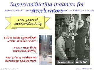
Magnetrons for accelerators Amos Dexter PLAN • History • Opportunities • Current status • Magnetron efficiency • Magnetron phase locking
The Reflection Amplifier Cavity Load Magnetron Circulator Injection Source • Linacs require accurate phase control • Phase control requires an amplifier • Magnetrons can be operated as reflection amplifiers Compared to Klystrons, in general Magnetrons - are smaller - more efficient - can use permanent magnets - utilise lower d.c. voltage but higher current - are easier to manufacture Consequently they are much cheaper topurchase and operate J. Kline “The magnetron as a negative-resistance amplifier,” IRE Transactions on Electron Devices, vol. ED-8, Nov 1961 H.L. Thaland R.G. Lock, “Locking of magnetrons by an injected r.f. signal”, IEEE Trans. MTT, vol. 13, 1965
History Single magnetrons 2.856 GHz, 5 MW, 3ms pulse, 200 Hz repetition are used to power linacs for medical and security applications. Multiple magnetrons have been considered for high energy normal conducting linacs but the injection power needed for an unstabilised magnetron made it uncompetitive with a Klystron. J.C. Slater “The Phasing of Magnetrons” MIT Technical Report 35, 1947 Overett, T.; Bowles, E.; Remsen, D. B.; Smith, R. E., III; Thomas, G. E. “ Phase Locked Magnetrons as Accelerator RF Sources” PAC 1987 Benford J., Sze H., Woo W., Smith R., and Harteneck B., “Phase locking of relativistic magnetrons”Phys. Rev.Lett., vol. 62, no. 4, pp. 969, 1989. Treado T. A., Hansen T. A., and Jenkins D.J. “Power-combining and injection locking magnetrons for accelerator applications,” Proc IEEE Particle Accelerator Conf., San Francisco, CA 1991. Chen, S. C.; Bekefi, G.; Temkin, R. J. “ Injection Locking of a Long-Pulse Relativistic Magnetron” PAC 1991 Treado, T. A.; Brown, P. D.; Hansen, T. A.; Aiguier, D. J. “ Phase locking of two long-pulse, high-power magnetrons” , IEEE Trans. Plasma Science, vol 22, p616-625, 1994 Treado, Todd A.; Brown, Paul D., Aiguier, Darrell “New experimental results at long pulse and high repetition rate, from Varian's phase-locked magnetron array program” Proceedings Intense Microwave Pulses, SPIE vol. 1872, July 1993 Courtesy of e2v
Low Noise State for Cooker Magnetrons The Magnetron A Low Noise, Long Life Amplifier This author, a leading proponent of the transmission of power via microwave beams, describes how the common microwave oven magnetron can be externally locked to provide 30 .dB of gain - resulting in a 500 watt, 70% efficient, $15, coherent microwave source. William C. Brown Consultant Weston, Massachusetts The 2450 MHz magnetron which supplies 700 watts of average power to the ubiquitous microwave oven is made in a quantity of 15,000,000 units annually at a very low price, less than $15. It has a high conversion efficiency of 70% and small size and mass. What is not generally recognized is that it has very low noise and long life properties, and that it can be combined with external circuitry to convert it into a phase-locked amplifier with 30 dB gain, without compromising its noise or life properties. Such amplifiers are ideal for combining with slot ted waveguide radiators to form radiating modules in a low-cost , electronically steerable phased array for beamed power , which motivated this study. However, there are conceivably numerous other practical purposes for which these properties can be utilized. The low noise and long life properties are associated with a feedback mechanism internal to the magnetron that hold s the emission capabilities of the cathode to those levels consistent with both low noise and Jong life. This internal feedback mechanism is effective when the magnetron is operated from a relatively well filtered DC power supply with the cathode heated by back bombardment power alone. APPLIED MICROWAVE Summer 1990
Pushing Curves and Low Noise State These measurements were made with the magnetron running in a phase locked loop. Anode current is varies as the external match is varied. Pushing for Panasonic 2M137 Low noise state associated with low heater power and low anode current
Opportunities Our conceptual application was for intense proton beams as would be required for a neutrino factory or future spallation sources. Magnetrons can become an option for intense proton beams where they give significantly greater efficiency than other devices and bring down the lifetime cost of the machine without sacrificing performance and reliability. The easiest applications are where beam quality is not a key issue.
A Magnetron Solution for SPL? https://indico.cern.ch/event/63935/session/1/contribution/73 Permits fast phase control but only slow, full range amplitude control A substantial development program would be required for a 704 MHz, 880 kW long pulse magnetron Cavity Standard Modulator 880 kW Magnetron Load 4 Port Circulator Pulse to pulse amplitude can be varied Slow tuner LLRF ~ -13 dB to -17 dB needed for locking i.e. between 18 kW and 44kW hence between 42 kW and 16 kW available for fast amplitude control 60 kW IOT Could fill cavity with IOT then pulse magnetron when beam arrives
Magnetron Exciting Superconducting cavity Demonstration of CW 2.45 GHz magnetron driving a specially manufactured superconducting cavity in a vertical test facility at JLab and the control of phase in the presence of microphonics was successful. First demonstration and performance of an injection locked continuous wave magnetron to phase control a superconducting cavity A.C. Dexter, G. Burt, R. Carter, I. Tahir, H. Wang, K. Davis, and R. Rimmer, Physical Review Special Topics: Accelerators and Beams, Vol. 14, No. 3, 17.03.2011, p. 032001. http://journals.aps.org/prstab/abstract/10.1103/PhysRevSTAB.14.032001
Protons at FermiLab FERMILAB-PUB-13-315-AD-TD High-power magnetron transmitter as an RF source for superconducting linear accelerators GrigoryKazakevich*,Rolland Johnson, Gene Flanagan, Frank Marhauser, Muons, Inc., Batavia, 60510 IL, USA Vyacheslav Yakovlev, Brian Chase, ValeriLebedev, Sergei Nagaitsev, Ralph Pasquinelli, Nikolay Solyak, Kenneth Quinn, and Daniel Wolff, Fermilab, Batavia, 60510 IL, USA Viatcheslav Pavlov, Budker Institute of Nuclear Physics (BINP), Novosibirsk, 630090, Russia A concept of a high-power magnetron transmitter based on the vector addition of signals of two injection-locked Continuous Wave (CW) magnetrons, intended to operate within a fast and precise control loop in phase and amplitude, is presented. This transmitter is proposed to drive Superconducting RF (SRF) cavities for intensity-frontier GeV-scale proton/ion linacs, such as the Fermilab Project X 3 GeV CW proton linac or linacs for Accelerator Driven System (ADS) projects. The transmitter consists of two 2-cascade injection-locked magnetrons with outputs combined by a 3- dB hybrid. In such a scheme the phase and power control are accomplished by management of the phase and the phase difference, respectively, in both injection-locked magnetrons, allowing a fast and
Efficiency For good efficiency need to have slow electrons hitting the anode. Simple estimate J.C.Slater, “Microwave Electronics”, Reviews of Modern Physics, Vol 18, No 4, 1946 • High magnetic field important for good efficiency • Can high efficiency be achieved when magnetron is injection locked? • Low external Q is needed for stable locking over a useable bandwidth • Low external Q is good for efficiency
PIC Code Modelling RF Output RF Input efficient Cathode B field into page inefficient Have used VORPAL and MAGIC to simulate magnetrons Takes a huge amount of time to get a single operating point Gets impedance incorrect for efficient cooker magnetrons Prefer to assume RF field and compute trajectories in a self consistent d.c. field
VORPAL model of 2M137 Panasonic magnetron 5.6 ns 6.0 ns 5.2 ns 11.15ns 38.60 ns 23.1 ns 37.40 ns 36.24 ns 41.00 ns 39.42 ns 45.80 ns 39.80 ns
Magnetron Start Up • No RF seeding /RF injection has been used in previous slide. • Spoke growth requires noise. The noise comes from mesh irregularities and random emission. • Start up time is mesh dependent. • Start also requires sufficient charge to collect in cathode anode gap. • Without random emission and mesh irregularity all electrons return to cathode and the magnetron does not start. • Once the rotating charge has a certain density and extent, the spokes form very quickly. • A lot of time is wasted with PIC models waiting for the magnetron to start. • Conversely a problem with steady state models is that one does not necessarily know how to get to the operating point that was modelled.
Magnetron Operation Panasonic 2M137 Results from a self consistent model with a coiled cathode Electrons can leave from any point on coil hence emission points are within the inner circle marking the outside radius of the cathode Electrons can spiral between turns contributing to space charge at the cathode. If the electrons become synchronous with the RF then they move to the anode in about 5 arcs. Most electrons return to the cathode.
Orbits in high efficiency 2.45 GHz cooker design CATHODE B = 2.2T, V = 4000, IA=1.13A, VRF=2450V, P=3.86kW, Eff = 86%, Solid Cathode 1880K
Field in high efficiency 2.45 GHz cooker design At this operating point the field at cathode is just negative. Field at cathode becomes positive as cathode temperature increases or anode current decreases. To get a stable calculation mesh size near cathode ~ 2 microns Efficiency peaks as tops of cusps coincide with anode. Calculations are not fully realistic as to change the RF voltage one has to change external Q and this changes the frequency
Orbits for 1 MW 704 MHz design An efficient orbit should have no loop, electronic efficiency prediction ~ 96%
Reflection Amplifier Controllability 0o towards magnetron Arcing Moding 900 W 800 W 700 W VSWR 6 2 3 4 90o 270o +5MHz +2.5MHz -5MHz +0MHz -2.5MHz 180o • Phase of output follows the phase of the input signal • Phase shift through magnetron depends on difference between input frequency and the magnetrons natural frequency • Output power has minimal dependence on input signal power (Should add) • Phase shift through magnetron depends on input signal power • There is a time constant associated with the output phase following the input phase • Magnetron frequency and output vary together as a consequence of • Varying the magnetic field • Varying the anode current (pushing) • Varying the reflected power (pulling) 915MHz 916MHz Anode Voltage 10kW 20kW 30kW 40kW 3.00A 12.0 kV 11.5 kV 2.92A Power supply load line 2.85A 11.0 kV 2.78A 10.5 kV 2.70A Magnetic field coil current 10.0 kV 1 2 3 4 5 Anode Current Amps
Spectrum with PLL frequency control Heater Power = 4.2W Bandwidth ~ 100 kHz
Phase & Freq Shift Keying Injection Locked Magnetron The performance of a magnetron in the control loop of a phase locked accelerator cavity depends on its bandwidth. Its bandwidth determines how quickly it can respond to a new required phase.
Frequency Shift Keying Input to pin diode Output from double balanced mixer after mixing with 3rd frequency Lower trace is output from double-balance mixer when magnetron injection signal is switched from 2.452 to 2.453 GHz at a rate of 250 kb/s (upper trace) and referenced to 2.451 GHz.
Response as function of heater power Input wave 8 W heater 15 W heater 36 W heater 43 W heater Mismatch ~13% reflected power at 100 deg towards load. Matched.
Phase Control in Warm Cavity Double Balance Mixer Oscilloscope 2 Stub Tuner 2 Loop Coupler 3 Stub Tuner 1 Water Load Loop Coupler Circulator 1 10 Vane Magnetron Water Load 1W Amplifier Circulator 2 C3 Load Power supply ripple IQ Modulator (Amplitude & phase shifter) D/A Oscilloscope A/D D/A Magnetron phase no LLRF DSP LP Filter 8 kHz cut-off Digital Phase Detector 1.3GHz D/A ÷ M ÷ M pk-pk 26o High Voltage Transformer Magnetron phase with LLRF pk-pk 1.2o Micro-Controller 40kHz Chopper Frequency Divider / N 2.3 - 2.6 GHz PLL Oscillator ADF4113 + VCO 10 MHz TCXO 1ppm Pulse Width Modulator SG 2525 Divider / R 1.5 kW Power Supply Phase - Freq Detector & Charge Pump Loop Filter 325 V DC + 5% 100 Hz ripple ADF 4113
Prospects • Intense beams in user facilities need to be generated efficiently. • Developing a new HPRF source is expensive and comparison to available sources is difficult before development is mature. • Would not use magnetron for a superconducting linacif klystron affordable. • Universities will continue to explore new concepts. • Need accelerator labs to explore new devices at accelerator test stands to have any chance of new devices becoming feasible alternatives. • Future accelerators constrained on cost so research on efficient low cost sources is worthwhile.
SCRF cavity powered with magnetron Injection + magnetron on +control Injection but magnetron off Injection + magnetron on