Download
1 / 26
260 likes | 288 Views
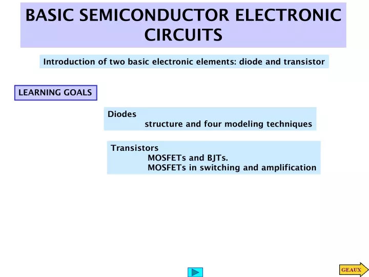
BASIC SEMICONDUCTOR ELECTRONIC CIRCUITS. Introduction of two basic electronic elements: diode and transistor. LEARNING GOALS. Diodes structure and four modeling techniques. Transistors MOSFETs and BJTs. MOSFETs in switching and amplification. PASSIVE DEVICES IN INTEGRATED CIRCUITS.

E N D
BASIC SEMICONDUCTOR ELECTRONIC CIRCUITS Introduction of two basic electronic elements: diode and transistor LEARNING GOALS Diodes structure and four modeling techniques Transistors MOSFETs and BJTs. MOSFETs in switching and amplification
PASSIVE DEVICES IN INTEGRATED CIRCUITS Inductor Capacitor Resistor
I-V convention Ideal diode I - V curve Ideal diode Forward bias Ideal diode Reverse bias DIODES Structure Symbol
I - V curve of an actual diode Actual diode I - V characteristic Next we develop two approximations to the actual I - V curve
Constant voltage model I - V curve Circuit equivalent Piecewise linear model Comparison of models Circuit equivalent I - V curve
LEARNING EXAMPLE Forward bias Diode is forward biased by the source Diode is reverse biased Reverse bias
LEARNING EXAMPLE Simplifying assumption When diodes are reverse biased Thevenin equivalent of driving network Under-voltage with piecewise linear model Under-voltage protection model using diode constant voltage model Analyze the protection circuit using diode models Using source superposition Using a similar way for over-voltage The figure in the next slide compares the three models
Simplifying assumption When diodes are reverse biased Is=1e-14;% MATLAB SCRIPT TO ANALYZE n=1; %UNDER-VOLTAGE Rs=40; vs=[-2:.2:2]'; vin=[]; for k=1:length(vs) x0=[vs(k);vs(k);Rs;Is]; kcl=inline('((x(2)-x(1))/x(3)+x(4)*(exp(-39*x(1))-1))^2'); x=fminsearch(kcl,x0); vin=[vin;x(1)]; end plot(vs,vin,'bo',vs,vin,'r'), title('UNDER-VOLTAGE WITH NONLINEAR DIODE') xlabel('Source Voltage(v_S)[V]'), ylabel('Input Voltage(v_{in})[V]'),grid Analysis using non linear diode model Under-voltage scenario. Top diode open Implicit function. Must be evaluated numerically
Bulk internally connected to source Cutoff state threshold conducting TRANSISTORS STRUCTURE OF MOSFETs The oxide is an insulator allowing zero current into the gate The gate voltage controls resistance from source to drain (in linear range)
Complete characteristics of n-channel MOSFET Linear characteristic N - channel MOSFET in the linear range
Linear model for BJT in active mode STRUCTURE OF BJTs (Bipolar Junction Tansistors)
Cutoff (switch open) ‘Switch closed’ Basic switching circuit MODELING MOSFET SWITCHING APPLICATIONS Typical values range from a few hundred Ohms for low-current applications to milli-ohms for currents in the tens of Amperes Linear Region Cutoff In the next slide we quantify this non-ideal behavior
LEARNING EXAMPLE The MOSFET is used as switch to energize and de-energize an inductor. Determine the output voltage with the “switch closed” Circuit after all transients have subsided (R=1 Ohm)
LEARNING EXAMPLE The MOSFET is used to switch 10A of current. The voltage drop across the FET in the on state must be less than 4% of the supply voltage. Find the maximum value of R_on
Due to non-zero slope of I - V curves in saturation Linear (small signals) model for MOSFET MODELING AMPLIFIER APPLICATIONS MOSFET in saturation
Define drain-source current. Together with bias voltage they define operating point Bias voltage. Helps to define location on I - V curve. The operating point determines the values of the parameters in the linear model Linear model relating changes in gate voltage to changes in output voltage MOSFET in saturation range Common Source Amplifier
LEARNING EXAMPLE PROBLEM If one must assure a gain of at least 50 in absolute value what should be the value for Rd? LEARNING EXAMPLE
LOAD Because there are dependent sources we must determine open-circuit voltage and short-circuit current Open circuit Small signals model Find the value of R_d such that maximum average power is transferred to the load at 30krad/s LEARNING EXAMPLE For maximum power transfer the Thevenin impedance of the amplifier must be the complex conjugate of the load
EXAMPLE (continued) Determination of short-circuit current
Practical implementation of booster Turns FET on or off. When FET is off diode becomes direct biased ANALYSIS OF A DC-DC CONVERTER When S2 is open and S1 closed, the inductor stores energy. A large capacitor helps to keep output voltage constant When S2 is closed and S1 open, the inductor transfers energy to capacitor Idealized circuit
Excel formula to compute W_L =$B$1^2*($B$4)^2/(2*($B$2)*($B$5)^2) Excel formula to compute Vo (cellD10) =SQRT(2*C10/$B$3-2*D9^2/($B$6*$B$3*$B$5)+D9^2) Plot of DC-DC converter output voltage USING EXCEL TO COMPUTE OUTPUT OF DC-DC CONVERTER
MATLAB SCRIPT TO COMPUTE AND PLOT THE BOOSTER OUTPUT %booster.m %Solves the booster circuit in BECA 7th Ed, page648 %%%%%%%%% define circuit parameters Vin=5; L=1e-5; C=1e-6; D=0.6; fs=1e5; Rload=200; %%%%%%%%% define iteration array n=[0:30]; tms=1e3*n/fs; %time in msec %%%%%%%%% initialize vectors and do one-time computations Wl=Vin^2*D^2/(2*L*fs^2); t1=2*Wl/C; kt2=1-2/(Rload*C*fs); vo=zeros(size(n)); %initialize output array %%%%%%%%% do the iterations for k=2:length(n) vo(k)=sqrt(t1+kt2*(vo(k-1))^2); end %%%%%%%%% display results plot(tms,vo,'bo',tms,vo,'r'),title('DC-DC CONVERTER OUPUT') xlabel('Time(ms)'),ylabel('V_o(V)'), grid
DIODES MOSFETs