Download
1 / 63
630 likes | 647 Views
Learn about MAC addresses, ARP protocol, and LAN addressing in the Data Link Layer of networking, including how devices communicate and route data packets between different LANs.

E N D
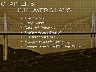
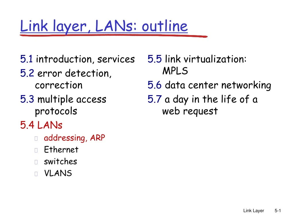
5.1introduction, services 5.2error detection, correction 5.3multiple access protocols 5.4 LANs addressing, ARP Ethernet switches VLANS 5.5 link virtualization: MPLS 5.6 data center networking 5.7 a day in the life of a web request Link layer, LANs: outline Link Layer
MAC Addresses and ARP • 32-bit IP address: • network-layer address • used to get datagram to destination IP subnet • MAC (or LAN or physical or Ethernet) address: • used to get datagram from one interface to another physically-connected interface (same network) • 48 bit MAC address (for most LANs) burned in the adapter ROM 5: DataLink Layer
1A-2F-BB-76-09-AD LAN (wired or wireless) 71-65-F7-2B-08-53 58-23-D7-FA-20-B0 0C-C4-11-6F-E3-98 LAN Addresses and ARP Each adapter on LAN has a unique LAN address Broadcast address = FF-FF-FF-FF-FF-FF = adapter 5: DataLink Layer
LAN Address (more) • MAC address allocation administered by IEEE • manufacturer buys portion of MAC address space (to assure uniqueness) • Each vendor registers one or more 3 octet OUIs (Organizationally Unique Identifier ) • http://www.macvendorlookup.com/ • Many Wireless LANs use MAC address for access control • MAC flat address ➜ portability • can move LAN card from one LAN to another • IP hierarchical address NOT portable • depends on IP subnet to which node is attached 5: DataLink Layer
Question: how to determine interface’s MAC address, knowing its IP address? ARP: address resolution protocol ARP table: each IP node (host, router) on LAN has table • IP/MAC address mappings for some LAN nodes: < IP address; MAC address; TTL> • TTL (Time To Live): time after which address mapping will be forgotten (typically 20 min) 137.196.7.78 1A-2F-BB-76-09-AD 137.196.7.23 137.196.7.14 LAN 71-65-F7-2B-08-53 58-23-D7-FA-20-B0 0C-C4-11-6F-E3-98 137.196.7.88 Link Layer
A wants to send datagram to B B’s MAC address not in A’s ARP table. A broadcasts ARP query packet, containing B's IP address dest MAC address = FF-FF-FF-FF-FF-FF all nodes on LAN receive ARP query B receives ARP packet, replies to A with its (B's) MAC address frame sent to A’s MAC address (unicast) A caches (saves) IP-to-MAC address pair in its ARP table until information becomes old (times out) soft state: information that times out (goes away) unless refreshed ARP is “plug-and-play”: nodes create their ARP tables without intervention from net administrator ARP protocol: same LAN Link Layer
111.111.111.110 E6-E9-00-17-BB-4B 222.222.222.222 49-BD-D2-C7-56-2A Addressing: routing to another LAN walkthrough: send datagram from A to B via R • focus on addressing – at IP (datagram) and MAC layer (frame) • assume A knows B’s IP address • assume A knows IP address of first hop router, R (how?) • assume A knows R’s MAC address (how?) B A R 111.111.111.111 74-29-9C-E8-FF-55 222.222.222.220 1A-23-F9-CD-06-9B 222.222.222.221 111.111.111.112 88-B2-2F-54-1A-0F CC-49-DE-D0-AB-7D Link Layer
MAC src: 74-29-9C-E8-FF-55 MAC dest: E6-E9-00-17-BB-4B IP src: 111.111.111.111 IP dest: 222.222.222.222 IP Eth Phy 111.111.111.110 E6-E9-00-17-BB-4B 222.222.222.222 49-BD-D2-C7-56-2A Addressing: routing to another LAN • A creates IP datagram with IP source A, destination B • A creates link-layer frame with R's MAC address as dest, frame contains A-to-B IP datagram B A R 111.111.111.111 74-29-9C-E8-FF-55 222.222.222.220 1A-23-F9-CD-06-9B 222.222.222.221 111.111.111.112 88-B2-2F-54-1A-0F CC-49-DE-D0-AB-7D Link Layer
MAC src: 74-29-9C-E8-FF-55 MAC dest: E6-E9-00-17-BB-4B IP src: 111.111.111.111 IP dest: 222.222.222.222 IP Eth Phy IP src: 111.111.111.111 IP dest: 222.222.222.222 IP Eth Phy 111.111.111.110 E6-E9-00-17-BB-4B 222.222.222.222 49-BD-D2-C7-56-2A Addressing: routing to another LAN • frame sent from A to R • frame received at R, datagram removed, passed up to IP B A R 111.111.111.111 74-29-9C-E8-FF-55 222.222.222.220 1A-23-F9-CD-06-9B 222.222.222.221 111.111.111.112 88-B2-2F-54-1A-0F CC-49-DE-D0-AB-7D Link Layer
IP Eth Phy MAC src: 1A-23-F9-CD-06-9B MAC dest: 49-BD-D2-C7-56-2A IP Eth Phy IP src: 111.111.111.111 IP dest: 222.222.222.222 111.111.111.110 E6-E9-00-17-BB-4B 222.222.222.222 49-BD-D2-C7-56-2A Addressing: routing to another LAN • R forwards datagram with IP source A, destination B • R creates link-layer frame with B's MAC address as dest, frame contains A-to-B IP datagram B A R 111.111.111.111 74-29-9C-E8-FF-55 222.222.222.220 1A-23-F9-CD-06-9B 222.222.222.221 111.111.111.112 88-B2-2F-54-1A-0F CC-49-DE-D0-AB-7D Link Layer
IP Eth Phy MAC src: 1A-23-F9-CD-06-9B MAC dest: 49-BD-D2-C7-56-2A IP Eth Phy IP src: 111.111.111.111 IP dest: 222.222.222.222 111.111.111.110 E6-E9-00-17-BB-4B 222.222.222.222 49-BD-D2-C7-56-2A Addressing: routing to another LAN • R forwards datagram with IP source A, destination B • R creates link-layer frame with B's MAC address as dest, frame contains A-to-B IP datagram B A R 111.111.111.111 74-29-9C-E8-FF-55 222.222.222.220 1A-23-F9-CD-06-9B 222.222.222.221 111.111.111.112 88-B2-2F-54-1A-0F CC-49-DE-D0-AB-7D Link Layer
IP Eth Phy MAC src: 1A-23-F9-CD-06-9B MAC dest: 49-BD-D2-C7-56-2A IP src: 111.111.111.111 IP dest: 222.222.222.222 111.111.111.110 E6-E9-00-17-BB-4B 222.222.222.222 49-BD-D2-C7-56-2A Addressing: routing to another LAN • R forwards datagram with IP source A, destination B • R creates link-layer frame with B's MAC address as dest, frame contains A-to-B IP datagram B A R 111.111.111.111 74-29-9C-E8-FF-55 222.222.222.220 1A-23-F9-CD-06-9B 222.222.222.221 111.111.111.112 88-B2-2F-54-1A-0F CC-49-DE-D0-AB-7D Link Layer
5.1introduction, services 5.2error detection, correction 5.3multiple access protocols 5.4 LANs addressing, ARP Ethernet switches VLANS 5.5 link virtualization: MPLS 5.6 data center networking 5.7 a day in the life of a web request Link layer, LANs: outline Link Layer
Ethernet “dominant” wired LAN technology: • cheap $20 for 100Mbs! • first widely used LAN technology • Simpler, cheaper than token LANs and ATM • Kept up with speed race: 10 Mbps – 10 Gbps Metcalfe’s Ethernet sketch Old cable-line ethernet 5: DataLink Layer
Bus topology • bus topology popular through mid 90s • all nodes in same collision domain (can collide with each other) 10BASE2 cable showing BNC Connector end 10BASE2 cable with BNC T-Connector. bus: coaxial cable 10BASE2 Pictures are from Wikipiedia 5: DataLink Layer
Star topology • today: star topology prevails • active switch in center • each “spoke” runs a (separate) Ethernet protocol (nodes do not collide with each other) switch star 5: DataLink Layer
Images from http://atom.klub.chip.pl/ 5: DataLink Layer
Ethernet Frame Structure Sending adapter encapsulates IP datagram (or other network layer protocol packet) in Ethernet frame Preamble: • 7 bytes with pattern 10101010 followed by one byte with pattern 10101011 • used to synchronize receiver, sender clock rates MAC addr CRC-32 5: DataLink Layer
Ethernet Frame Structure (more) • Addresses: 6 bytes • if adapter receives frame with matching destination address, or with broadcast address (eg ARP packet), it passes data in frame to net-layer protocol • otherwise, adapter discards frame • Type: indicates the higher layer protocol (mostly IP but others may be supported such as Novell IPX and AppleTalk) • CRC: checked at receiver, if error is detected, the frame is simply dropped 5: DataLink Layer
Unreliable, connectionless service • Connectionless: No handshaking between sending and receiving adapter. • Unreliable: receiving adapter doesn’t send acks or nacks to sending adapter • Data field is 46bytes -1,500 bytes • If data less than 46 bytes, stuff to be 46bytes • Network layer uses “length” field to remove stuffing. 5: DataLink Layer
No slots (no sync clock) Preamble in Ethernet frame is used to sync clock between sender and receiver adapter doesn’t transmit if it senses that some other adapter is transmitting, that is, carrier sense transmitting adapter aborts when it senses that another adapter is transmitting, that is, collision detection Before attempting a retransmission, adapter waits a random time, that is, random access Ethernet uses CSMA/CD 5: DataLink Layer
1. Adaptor receives datagram from net layer & creates frame 2. If adapter senses channel idle, it starts to transmit frame. If it senses channel busy, waits until channel idle and then transmits 3. If adapter transmits entire frame without detecting another transmission, the adapter is done with frame ! 4. If adapter detects another transmission while transmitting, aborts and sends jam signal (48-bit, Why?) 5. After aborting, adapter enters exponential backoff: after the m-th collision, adapter chooses a K at random from {0,1,2,…,2m-1}. Adapter waits K·512 bit times and returns to Step 2 Ethernet CSMA/CD algorithm 5: DataLink Layer
Jam Signal: make sure all other transmitters are aware of collision; 48 bits Bit time: .1 microsec for 10 Mbps Ethernet ;for K=1023, wait time is about 50 msec Exponential Backoff: Goal: adapt retransmission attempts to estimated current load heavy load: random wait will be longer first collision: choose K from {0,1}; delay is K· 512 bit transmission times after second collision: choose K from {0,1,2,3}… after ten collisions, choose K from {0,1,2,3,4,…,1023} Ethernet’s CSMA/CD (more) Why exponential? Why random number picking? 5: DataLink Layer
CSMA/CD efficiency • Tprop = max prop between 2 nodes in LAN • ttrans = time to transmit max-size frame • Efficiency goes to 1 as tprop goes to 0 • Goes to 1 as ttrans goes to infinity • Much better than ALOHA, but still decentralized, simple, and cheapWhy? 5: DataLink Layer
application transport network link physical fiber physical layer copper (twister pair) physical layer 802.3 Ethernet Standards: Link & Physical Layers • many different Ethernet standards • common MAC protocol and frame format • different speeds: 2 Mbps, 10 Mbps, 100 Mbps, 1Gbps, 10G bps • different physical layer media: fiber, cable MAC protocol and frame format 100BASE-T2 100BASE-FX 100BASE-TX 100BASE-BX 100BASE-SX 100BASE-T4 5: DataLink Layer
Manchester encoding • Used in 10BaseT • Each bit has a transition • Allows clocks in sending and receiving nodes to synchronize to each other • no need for a centralized, global clock among nodes! • Hey, this is physical-layer stuff! 5: DataLink Layer
5.1introduction, services 5.2error detection, correction 5.3multiple access protocols 5.4 LANs addressing, ARP Ethernet switches VLANS 5.5 link virtualization: MPLS 5.6 data center networking 5.7 a day in the life of a web request Link layer, LANs: outline Link Layer
twisted pair hub 10BaseT and 100BaseT • 10/100 Mbps rate; latter called “fast ethernet” • T stands for Twisted Pair • Nodes connect to a hub: “star topology”; 100 m max distance between nodes and hub 5: DataLink Layer
twisted pair hub Hubs Hubs are essentially physical-layer repeaters: • bits coming from one link go out all other links • at the same rate • no frame buffering • no CSMA/CD at hub: adapters detect collisions • provides net management functionality 5: DataLink Layer
Switch • link-layer device: smarter than hubs, take active role • store, forward Ethernet frames • examine incoming frame’s MAC address, selectively forward frame to one-or-more outgoing links when frame is to be forwarded on segment, uses CSMA/CD to access segment • transparent • hosts are unaware of presence of switches • plug-and-play, self-learning • switches do not need to be configured 5: DataLink Layer
Switch: allows multiple simultaneous transmissions A • hosts have dedicated, direct connection to switch • switches buffer packets • Ethernet protocol used on each incoming link, but no collisions; full duplex • each link is its own collision domain • switching:A-to-A’ and B-to-B’ simultaneously, without collisions • not possible with dumb hub C’ B 1 2 3 6 4 5 C B’ A’ switch with six interfaces (1,2,3,4,5,6) 5: DataLink Layer
Switch Table A • Q: how does switch know that A’ reachable via interface 4, B’ reachable via interface 5? • A: each switch has a switch table, each entry: • (MAC address of host, interface to reach host, time stamp) • looks like a routing table! • Q: how are entries created, maintained in switch table? • something like a routing protocol? C’ B 1 2 3 6 4 5 C B’ A’ switch with six interfaces (1,2,3,4,5,6) 5: DataLink Layer
Source: A Dest: A’ MAC addr interface TTL 60 1 A A A’ Switch: self-learning A • switchlearns which hosts can be reached through which interfaces • when frame received, switch “learns” location of sender: incoming LAN segment • records sender/location pair in switch table C’ B 1 2 3 6 4 5 C B’ A’ Switch table (initially empty) 5: DataLink Layer
Filtering/Forwarding When switch receives a frame: index switch table using MAC dest address if entry found for destinationthen{ if dest on segment from which frame arrivedthen drop the frame else forward the frame on interface indicated } else flood forward on all but the interface on which the frame arrived 5: DataLink Layer
Interconnecting switches • switches can be connected together S4 S1 S3 S2 A F I D C B H G E • Q: sending from A to G - how does S1 know to forward frame destined to F via S4 and S3? • A:self learning! (works exactly the same as in single-switch case!) Link Layer
Institutional network mail server to external network web server router IP subnet Link Layer
Switches vs. Routers • both store-and-forward devices • routers: network layer devices (examine network layer headers) • switches are link layer devices • routers maintain routing tables, implement routing algorithms • switches maintain switch tables, implement filtering, learning algorithms 5: DataLink Layer
Summary comparison 5: DataLink Layer
VLANs: motivation (virtual LAN) consider: • CS user moves office to EE, but wants connect to CS switch? • single broadcast domain: • all layer-2 broadcast traffic (ARP, DHCP, unknown location of destination MAC address) must cross entire LAN • security/privacy, efficiency issues Computer Science Computer Engineering Electrical Engineering Link Layer
7 1 2 8 15 9 10 16 VLANs Virtual Local Area Network port-based VLAN: switch ports grouped (by switch management software) so that singlephysical switch …… 15 7 9 1 2 8 10 16 switch(es) supporting VLAN capabilities can be configured to define multiple virtualLANS over single physical LAN infrastructure. … … Computer Science (VLAN ports 9-15) Electrical Engineering (VLAN ports 1-8) … operates as multiplevirtual switches … … Computer Science (VLAN ports 9-16) Electrical Engineering (VLAN ports 1-8) Link Layer
forwarding between VLANS: done via routing (just as with separate switches) • in practice vendors sell combined switches plus routers Port-based VLAN router • traffic isolation:frames to/from ports 1-8 can only reach ports 1-8 • can also define VLAN based on MAC addresses of endpoints, rather than switch port 15 7 9 1 2 8 10 16 • dynamic membership: ports can be dynamically assigned among VLANs … … Computer Science (VLAN ports 9-15) Electrical Engineering (VLAN ports 1-8) Link Layer
1 16 VLANS spanning multiple switches • trunk port:carries frames between VLANS defined over multiple physical switches • frames forwarded within VLAN between switches can’t be vanilla 802.1 frames (must carry VLAN ID info) • 802.1q protocol adds/removed additional header fields for frames forwarded between trunk ports 15 7 9 7 1 3 5 2 8 10 4 6 2 8 … … Computer Science (VLAN ports 9-15) Ports 2,3,5 belong to EE VLAN Ports 4,6,7,8 belong to CS VLAN Electrical Engineering (VLAN ports 1-8) Link Layer
802.1Q VLAN frame format type source address dest. address preamble data (payload) 802.1 frame CRC type 802.1Q frame data (payload) CRC 2-byte Tag Protocol Identifier (value: 81-00) Recomputed CRC Tag Control Information (12 bit VLAN ID field, 3 bit priority field like IP TOS) source address dest. address preamble Link Layer
5.1introduction, services 5.2error detection, correction 5.3multiple access protocols 5.4 LANs addressing, ARP Ethernet switches VLANS 5.5 link virtualization: MPLS 5.6 data center networking 5.7 a day in the life of a web request Link layer, LANs: outline Link Layer
Multiprotocol label switching (MPLS) • initial goal: high-speed IP forwarding using fixed length label (instead of IP address) • fast lookup using fixed length identifier (rather than shortest prefix matching) • borrowing ideas from Virtual Circuit (VC) approach • but IP datagram still keeps IP address! PPP or Ethernet header IP header remainder of link-layer frame MPLS header label Exp TTL S 5 1 3 20 Link Layer
MPLS capable routers • a.k.a. label-switched router • forward packets to outgoing interface based only on label value (don’t inspect IP address) • MPLS forwarding table distinct from IP forwarding tables • flexibility: MPLS forwarding decisions can differ from those of IP • use destination and source addresses to route flows to same destination differently (traffic engineering) • re-route flows quickly if link fails: pre-computed backup paths (useful for VoIP) Link Layer
MPLS versus IP paths R6 D R4 R3 R5 A R2 • IP routing: path to destination determined by destination address alone IP router Link Layer
MPLS versus IP paths entry router (R4) can use different MPLS routes to A based, e.g., on source address R6 D R4 R3 R5 A R2 • IP routing: path to destination determined by destination address alone IP-only router • MPLS routing: path to destination can be based on source and dest. address • fast reroute: precompute backup routes in case of link failure MPLS and IP router Link Layer
5.1introduction, services 5.2error detection, correction 5.3multiple access protocols 5.4LANs addressing, ARP Ethernet switches VLANS 5.5 link virtualization: MPLS 5.6 data center networking 5.7 a day in the life of a web request Link layer, LANs: outline Link Layer
Data center networks • 10’s to 100’s of thousands of hosts, often closely coupled, in close proximity: • e-business (e.g. Amazon) • content-servers (e.g., YouTube, Akamai, Apple, Microsoft) • search engines, data mining (e.g., Google) • challenges: • multiple applications, each serving massive numbers of clients • managing/balancing load, avoiding processing, networking, data bottlenecks Inside a 40-ft Microsoft container, Chicago data center Link Layer