Download
1 / 15
150 likes | 172 Views
3-D Modeling Concepts. V106.02 part B. Basic Modeling. All 3D modeling programs contain certain basic geometric shapes that can be combined with or subtracted from other shapes to form more complex objects.

E N D
3-D Modeling Concepts V106.02 part B
Basic Modeling • All 3D modeling programs contain certain basic geometric shapes that can be combined with or subtracted from other shapes to form more complex objects. • Some programs contain more objects than others, but a sample list of basic primitives includes: • Sphere • Cube or box • Cylinder • Torus • Cone • Plane
Basic Modeling • Arcs, ellipses, circles, curves, and freehand curves are basic 2D shapes typically provided within modeling programs. Shapes may be combined to create complex objects. • Splines are curves or polygons that are composed of segments that can be manipulated by control pointsplaced along the curve. • Control points may be made “active” and then dragged using a handle attached to the point.
Basic Modeling • Polygons are plane figures made with three or more straight sides (curves). • Regular polygonshave equal length sides and equal angles.
Basic Modeling • Some programs require the user to define parameters of the primitive prior to importing it into the scene; others will bring in a “standard” sized object and place it in a selected position. • Typical parameters include center point, radius, height, width, etc.
Basic Modeling • Parameters affect the size, placement, and orientation of the object. • Values provided automatically by the software are called the defaults. A typical default would be to bring in an object oriented in a certain direction with respect to a construction plane.
Modeling Techniques • Booleantools or operations are used to create objects by combining, subtracting, or determining the common intersections of various objects such as primitives. • Union or Addition(+ or ) is used to combine objects together into one new object. • Subtract or Difference() is used to remove part or all of an object where objects overlay each other. • Intersection (* or ) is used to calculate the overlapping volumes of objects so that the overlap becomes the object. • Named for the British mathematician George Boole.
Modeling Techniques • Extrusion,sweeping, or loftingallows you to create a 2D shape and then extend it along a path or curve to form a 3D object. The 2D shape may be open (curves that do not connect back onto the beginning or closed (lines connect back onto the beginning). • *Note- Nurbs or spline modeling are limited in use in basic 3d modeling. Training in this course will be based on “box modeling” and spline modeling concepts.
Modeling Techniques • A variation of sweeping is lofting, where a series of curves (open or closed) is lofted or spaced parallel to each other, and then a is generated that connects the contours. • Lofting may also be done using asurface profile shape and a curve along which the profile is lofted. An example of where lofting is used would be for modeling boat hulls and terrains.
Modeling Techniques • Revolve or lathe operations allow the user to create a 2D shape and then revolve it around an axis. • Lathe operations emulate the lathe found in manufacturing shops. A lathe is a tool used to rotate and shape material by bringing cutting tools against the material while it spins. • The revolution may be a full 360 degrees or any smaller angle. • Lathe operations are often used to model objects such as bowls, bottles, and dishes.
Modeling Techniques • Transformations or Transforms are actions that scale, rotate, and move objects • Scale changes the size or proportions of an object along one or more axes.
Modeling Techniques • Rotate refers to tilting or changing the direction that an object is facing. • Rotation is usually assigned to a particular axis. For example, the object might be rotated along its X-axis. • Most programs assign a default location for rotational axes. This location (pivot point) may need to be relocated to create to the desired movement. • Rotation is usually specified using degrees relative to a beginning point.
Modeling Techniques • Move is used to advance an object from one position to another. • Linear distance along the X-, Y-, or Z-axis is used to measure movement. • Movement may be constrained by a snap or grid setting. Snap allows the object to be moved only at set intervals of distance. • Movement can also be restricted to a grid so that the object jumps from grid line to grid line.
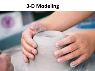
Modeling Techniques • Deformations are used to modify an existing shape. • Selected vertices, control points, polygon faces, or cross sections of an object may be used to control and influence the deformation process. • Deformation tools emulate the process of working a piece of clay. • Examples include taper, bend, twist, smooth, and stretch.
Modeling Techniques • Copy or Clonetools allow selected objects to be reproduced in their exact size and form. • Mirror tools allow selected shapes to be copied or flipped about a defined center.