Download
1 / 52
520 likes | 534 Views
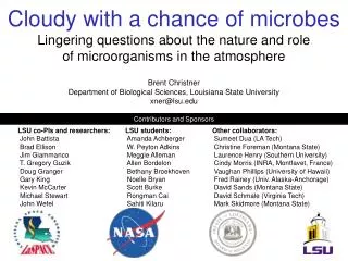
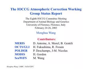
Contributors. R. Bruce, S. Redaelli, A. Rossi, B. Salvachua Ferrando (CERN), A. Valishev (Fermilab) Many thanks to

E N D
Contributors R. Bruce, S. Redaelli, A. Rossi, B. Salvachua Ferrando (CERN),A. Valishev (Fermilab) Many thanks to O. Aberle, A. Bertarelli, F. Bertinelli, O. Brüning, G. Bregliozzi, P. Chiggiato, S. Claudet, R. Jones, Y. Muttoni, L. Rossi, B. Salvant, H. Schmickler, R. Steinhagen, G. Tranquille, G. Valentino (CERN), V. Moens (EPFL), G. Annala, G. Apollinari, M. Chung, T. Johnson, I. Morozov, E. Prebys, V. Previtali, G. Saewert, V. Shiltsev, D. Still, L. Vorobiev (Fermilab), R. Assmann (DESY), M. Blaskiewicz, W. Fischer, X. Gu (BNL), D. Grote (LLNL), H. J. Lee (Pusan National U., Korea), S. Li (Stanford U.), A. Kabantsev (UC San Diego), T. Markiewicz (SLAC), D. Shatilov (BINP)
What’s an electron lens? • Pulsed, magnetically confined, low-energy electron beam • Circulating beam affected by electromagnetic fields generated by electrons • Stability provided by strong axial magnetic fields superconducting solenoid 1–6 T 6 m total length protons electrons antiprotons overlap region collector 5-kV, 1-A electron gun thermionic cathode 200-ns rise time Tevatron electron lens conventional solenoids 0.1–0.4 T Shiltsev et al., Phys. Rev. ST Accel. Beams 11, 103501 (2008)
Electron gun Superconducting solenoid Collector Electron lens (TEL-2) in the Tevatron tunnel
First main feature: control of electron beam profile Current density profile of electron beam is shaped by cathode and electrode geometry and maintained by strong solenoidal fields Flat profiles for bunch-by-bunch betatron tune correction Hollow profile for halo scraping Gaussian profile for compensation of nonlinear beam-beam forces
Second main feature: pulsed electron beam operation bunch spacing: 396 ns PROTON BUNCHES: ANTIPROTON BUNCHES: Beam synchronization in the Tevatron Pulsed electron beam could be synchronized with any group of bunches, with a different intensity for each bunch
Applications of electron lenses TEL-2 CDF TEL-1 0.98-TeV antiprotons 0.98-TeV protons DZero 2 km • In the Fermilab Tevatron collider • long-range beam-beam compensation (tune shift of individual bunches) • Shiltsev et al., Phys. Rev. Lett. 99, 244801 (2007) • abort-gap cleaning (for years of regular operations) • Zhang et al., Phys. Rev. ST Accel. Beams 11, 051002 (2008) • studies of head-on beam-beam compensation • Stancari and Valishev, FERMILAB-CONF-13-046-APC • demonstration of halo scraping with hollow electron beams • Stancari et al., Phys. Rev. Lett. 107, 084802 (2011) • Presently, being commissioned in RHIC at BNL • head-on beam-beam compensation • status in W. Fischer’s talk at IPAC14 • Current areas of research • generation of nonlinear integrable latticesin the Fermilab Integrable Optics Test Accelerator • hollow electron beam scraping of protons in LHC • as charged, current-carrying “wires” forlong-range beam-beam compensation in LHC • to generate tune spread for Landau dampingof instabilities before collisions in LHC Tevatron electron lenses
Concept of hollow electron beam collimator or scraper • Beam core is unaffected (field-free region) • Halo experiences nonlinear, tunable, possibly pulsed transverse kicks: No metal close to the high-power beam: no material damage or impedance Shiltsev, BEAM06, CERN-2007-002 Shiltsev et al., EPAC08
Hollow beam collimation with Tevatron electron lenses protons electrons antiprotons collector 5-kV, 1-A electron gun thermionic cathode 200-ns rise time conventional solenoids 0.1–0.4 T Tunable transverse halo kicks ~0.1 μrad
Hollow electron beam collimation studies in the Tevatron • Tevatron studies (Oct. ‘10 - Sep. ’11) provided experimental foundation • Main results: • compatible with collider operations • beam alignment is reliable and reproducible • halo removal is controllable, smooth, and detectable • negligible particle removal or emittance growth in the core • loss spikes due to beam jitter and tune adjustments are suppressed • effect of electron beam on halo fluxes and diffusivities vs. amplitude can be directly measured with collimator scans Stancari et al., Phys. Rev. Lett. 107, 084802 (2011) Stancari et al., IPAC11 (2011) Stancari, APS/DPF Proceedings, arXiv:1110.0144 [physics.acc-ph]
Relative scraping of 1 pbar bunch train vs. electron hole radius Particle removal is detectable and smooth 1.32%/h 5.18%/h No effect on core
Collimation and beam halo are critical for LHC • LHC and HL-LHC represent huge leaps in stored beam energy • No scrapers exist in LHC for full beam at top energy • The collimation system has performed very well so far (6σ half gaps, 140 MJ @ 4 TeV): efficiency, robustness • About 40 fills lost in 2012 due to instabilities (interplay of collimator impedance and beam-beam effects?) • Minimum design HL-LHC lifetimes (e.g., slow losses during squeeze/adjust) are close to plastic deformation of primary and secondary collimators: (692 MJ) / (0.2 h) = 1 MW • Significant program of collimation system upgrades under way
Collimation and beam halo are critical for HL-LHC • Halo populations (e.g., 4σ to 6σ) in LHC are poorly known. Collimator scans and van-der-Meer scans indicate 0.1-5% of total energy, which translates to 0.7 MJ to 35 MJ at 7 TeV. • Quench limits, magnet damage, or even collimator deformation will be reached with fast crab-cavity failures (~2σ orbit shift) or other fast losses • Hence the need to measure and monitor the halo, and to remove it at controllable rates. Beam halo monitoring and control are one of the major risk factors for HL-LHC and for safe operation with crab cavities • Hollow electron lenses are the most established and flexible tool for controlling the halo of high-power beams 4
A plan for electron lenses and halo control in LHC • Developed with LHC collimation team, within US LARP and HiLumi LHC • Final collimation needs and decisions can only be defined after gaining operational experience at 7 TeV (end of 2015) • uncertainties: cleaning efficiency, lifetimes, quench limits, impedances • Proceed with design of 2 devices: • conceptual design completed • technical design in 2014-2015 • construction 2015-2017, if needed • installation during 2018 long shutdown (2022 if limited by resources) • Investigate proposed alternative schemes (cheaper, available sooner?) • damper excitation, tune modulation, beam-beam wire compensators • Exchange electron lens hardware/software expertise with CERN • Develop noninvasive, direct halo diagnostics • If possible, extend Tevatron experience with beam tests at RHIC
The conceptual design report Available as FERMILAB-TM-2572-APC and as arXiv:1405.2033
Electron beam size is matched to proton beam size by solenoids cathode size magnetic compression 10-keV electrons 7-TeV protons
Example of numerical parameters for the LHC Overlap region L = 3 m Proton rms size Inner radius Outer radius Accelerating voltage Velocity Peak current Linear current density Max. kick 0.3 µrad for 7-TeV protons Charge and current densities For comparison: multiple Coulomb scattering in LHC primaries generates random kicks with spread θrms = 1.3 µrad Fields
Beam optics at candidate locations (LHC v6.503) Round beams, β ~ 200 m, low dispersion RB-46 RB-46
Pulsed operation of the electron lens in the LHC • Current state of the art of electron-lensmodulator rise time (10%-90%) is 200 nsat 5 kV • Pfeffer and Saewert, JINST 6, P11003 (2011) • This enables • turn-by-turn current modulation (stochastic or resonant) to enhance halo removal, if needed • train-by-train (900 ns separation), or possibly batch-by-batch (225 ns), operation • to preserve halo on a subset of bunches for machine protection • to compare different electron-lens settings for diagnostics • Bunch-by-bunch operation (25 ns) is not necessary for collimation
Summary of specifications All technical parameters are currently achievable
Hollow electron gun prototype for the LHC hollow cathode copper anode • 25 mm outer diameter, 13.5 mm inner diameter • Built and characterized at Fermilab electron-lens test stand
Performance of hollow electron gun prototype Yields 5 A at 10 kV
Numerical simulations: goals and tools • Would hollow electron beam collimation be effective in the LHC? • The kicks are nonlinear, with a small random component. Halo removal rates are expected to depend on magnetic rigidity of the beam, machine lattice, and noise sources. Nontrivial extrapolation from Tevatron to LHC. • Would there be any adverse effects on the core, such as lifetime degradation or emittance growth? • No effects were seen in the Tevatron in continuous mode. Effects of asymmetries in resonant operation? • Methods • Warp particle-in-cell code for electron beam dynamics with space charge • Lifetrac and SixTrack for numerical tracking • Machine models with nonlinearities • Uniform halo population, replenishing mechanisms to be implemented • Note: halo diffusion was measured in both Tevatron and LHC[Stancari et al., FERMILAB-CONF-13-054-APC, arXiv:1312.5007, Valentino et al., Phys. Rev. ST Accel. Beams 16, 021003 (2013)] • Ideal electron lens + imperfections (profile asymmetries, injection/extraction bends)
Dynamics of the magnetically confined electron beam • 3D simulation of electron beam propagation in electron lens with Warp particle-in-cell code [V. Moens, EPFL/CERN/Fermilab]: • Injection: space-charge limited e-gun or arbitrary particle coordinates • Layout: straight (test stand) or with bends (TEL-2 and LHC e-lens) • Computing resources • up to 1 m propagation calculable on multi-core laptop • parallel version installed on Fermilab cluster Gun 0.43 T Main 5 T Collector 0.43 T First use of particle-in-cell codes for electron-lens design Electron density in straight geometry
Effect of asymmetries in electron distribution on circulating beam No adverse effects were observed at the Tevatron in continuous operation, but application to the LHC may require higher beam currents and different pulsing patterns. We studied two sources of asymmetry: electrons 1. bends for injection/extraction 2. azimuthal asymmetries in overlap region
Azimuthal asymmetries in overlap region from measured profiles Calculated electric field [kV/m] for 1-A current, inner radius 4σp Fermilab electron-lens test stand Collector solenoid Gun solenoid Main solenoid Electron gun Collector Beam pipe Stands Platform Pinhole for current-density measurements Example of measured profile
Kick maps from injection and extraction bends: simplified approach proton beam axis 3D calculation of electric fields generated by a static, hollow charge distribution inside cylindrical beam pipes using Warp particle-in-cell code Electrostatic potential on the plane of the bend for 1 A, 5-keV electron beam (red = -1.2 kV, blue = 0 V) Symplectic kick maps are calculated by integrating electric fields over straight proton trajectories Stancari, FERMILAB-FN-0972-APC, arXiv:1403.6370 (2014)
Kick maps from injection and extraction bends Integrated fields (‘kicks’) [kV] vs. transverse proton position Horizontal Vertical For 7-TeV protons, 10 kV ⇒ 1.4 nrad
Simulation of HEBC at LHC • The goal is to produce estimate of the effect of HEBC on LHC beam • Main question: What magnitude of the removal rate for halo particles can be expected for realistic parameters of HEBC and LHC beams? • What is the impact of HEBC beam imperfections on the beam core/ luminosity lifetime. • Both in CONTINUOUS and STOCHASTIC mode • LHC Model • Lattice V6.503 with errors and beam-beam • HEBC element installed in RB46 at 39.26 m from IP4 • Single aperture restriction at 6σ (both x and y) • 10000 macro-particles, initial distribution – a ring with r1=4σ, r2=6σ • HEBC Model • Constant density, Inner beam radius 4σ • Current up to 3.6A Valishev, FERMILAB-TM-2584-APC (2014)
LHC HEBC Results • FMA shows new resonances and overall tune jitter for particles between 4 and 6 sigma HEBC off HEBC on
bb off bb on Halo Removal Rates 1.2A 2.4A 3.6A 40%/hr 4%/min 100%/min 100%/min
Effect of e- Bends 10% modulation 100% modulation • No impact in continuous mode • Stochastic mode • Significant horizontal emittance growth with U-layout (Tevatron EL) • Small emittance growth due to higher order harmonics with S-layoutLuminosity lifetime 90 hours (1%/hour).
Main results of numerical simulations • Continuous mode (= same electron current every turn for a given bunch) • halo removal times of hours (single beam) or minutes (collisions) • no adverse effects on proton beam core • Stochastic mode (= add turn-by-turn random noise to electron current) • halo removal times of minutes (independent of collisions) • some emittance growth due to bends • luminosity lifetime of 90 h with “S” configuration • A wide range of removal rates is possible • Continuous mode useful for smooth cleaning • Stochastic mode can be used for faster scraping(i.e. before squeeze and adjust) Valishev, FERMILAB-TM-2584-APC (2014)
Candidate locations for electron lenses in the LHC • Upstream or downstream of Point 4: • Available longitudinal space • Separation of beam axes: 420 mm • Cryogenic infrastructure • Lattice functions LHC IR4 RB-44
Mechanical integration studies for TEL2 • Rotation is necessary to avoid interference • New design of cryostat for LHC is preferable
Cryogenics • cryogenics dominates installation time: at least 3 months required for warm-up, connections, cool-down • electron lenses may be treated as stand-alone magnets at 4.5 K • may take advantage of dedicated rf refrigerator for HL-LHC at IR4 • TEL2 static heat loads: 12 W for He at 4 K and 25 W for liquid N2 shield • Tevatron magnet string liquid He flux was 90 l/s • N2 not available in LHC; use gaseous He at 20 bar? • integration of quench protection system • See A. Rossi’s talk at e-lens review: indico.cern.ch/event/213752 Likely main integration effort
Electrical systems • gun and collector solenoid power supplies: 340 A @ 0.4 T • main solenoid power supply: 1780 A @ 6.5 T • high voltage supplies for cathode, profiler, anode bias, collector: 10 kV • stacked-transformer modulator, anode pulsing: 10 kV, 35 kHz, 200 ns rise time No major challenges
Vacuum • 10-9 mbar typical in TEL2 with 3 ion pumps + Ti sublim. • Baking of inner surfaces • LHC requires vacuum isolation modules on each side (0.8 m each): gate valves, NEG cartridges, pumps, gauges • Surface certification • E-cloud stability (enhanced with solenoids on) • See also A. Rossi’s talk at e-lens review: indico.cern.ch/event/213752 Design needs to be reviewed according to LHC specifications
Diagnostics and instrumentation • corrector magnets for position and angle in main solenoid • accurate BPMs for both slow electron signals and fast proton signals • pickup and ion-clearing electrodes • sensitive (gated) loss monitors (scintillators, diamonds, ...) at nearest aperture • verify e-/p alignment • measure lifetimes, loss fluctuations, halo diffusivities vs. e-lens settings • electron beam diagnostics, following BNL designs • overlap with protons: backscattered electrons; also as sensitive halo monitor? • profiles with fluorescent screens (low current) and pinhole (high current)
Impedance • Very different bunch structure in Tevatron and LHC • Tight broad-band longitudinal impedance budget (90 mOhm) • Preliminary studies suggest that • modifications of Tevatron vacuum chamber and electrodes may be required for longitudinal fields, such as rf shields to suppress trapped modes • transverse impedance is acceptable More studies necessary, but no major obstacles so far
Resources and schedule • Construction cost of 2 devices for the LHC (1 per beam) is about 5 M$ in materials and 6 M$ in labor • Construction in 2015-2017 and installation in 2018 is technically feasible • Reuse of some Tevatron equipment is possible (superconducting coil, resistive solenoids, electron guns, ...) • Contributions to design, construction, commissioning, numerical simulations, beam studies, project management to be specified in CERN / US LARP agreement
Alternative halo removal techniques Are there halo-control options in LHC that are cheaper or that may be available sooner? • Tune modulation using warm quadrupoles • used at HERA to counteract power-supply ripple • O. Brüning and F. Willeke, EPAC94; Phys. Rev. Lett. 76, 3719 (1996) • Excitation with transverse dampers (W. Hofle) • Both methods work in tune space: halo not necessarily separated • Beam-beam wire compensator • Emittance preservation needs to be demonstrated • Simulations of effects on halo and core were started • Previtali et al., FERMILAB-TM-2560-APC (2013) • Simulation and hardware work at CERN led by R. Bruce
Long-range beam-beam compensation is essential for HL-LHC Plan B • HL-LHC Plan B: • flat optics at collisions: (10, 50) cm β* ⇒ no IP1/5 compensation • no crab cavities required (crab crossing/kissing improve performance) • a long-range beam-beamcompensation scheme is neededto achieve luminosity Koutchouk, PAC01 • Wire compensators at 10σ to be tested after LS1: technically challenging (378 A required) and a risk for collimation and machine protection • Electron lensesfor long-range beam-beam compensation are a safer, less demanding alternative, with pulsing option • (21 A) × (3 m) required for HL-LHC, any transverse shape • [Valishev and Stancari, arXiv:1312.1660] 5
Long-range beam-beam compensation with electron lenses • Preliminary work proceeding in parallel: • beam physics: expected performance, sensitivity to location • 2 options under study: • between D1 and D2 dipoles (challenging layout and integration) • beyond D2 dipole • energy deposition (superconducting solenoid) and radiation to electronics (anode high-voltage modulator) in both locations • integration issues LHC IR layout [from Fartoukh, Phys. Rev. ST Accel. Beams 16, 111002 (2013)]