Download
1 / 18
180 likes | 191 Views
Stabilization of the. Magnetic Field around the nEDM Apparatus at PSI. Introduction to n EDM. What is nEDM? neutron electric dipole moment d n current upper limit: 2.9 · 10 -26 e ·cm [90% CL] (1) Why is it interesting? How can d n be measured?

E N D
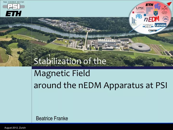
Stabilization of the Magnetic Field around the nEDM Apparatus at PSI
Introduction to nEDM • What is nEDM? neutronelectric dipole momentdn current upper limit: 2.9 · 10-26e·cm [90% CL] (1) • Why is it interesting? • How can dn be measured? • What does our experiment at PSI look like? (1) C.A.Baker et al., PRL 97, 131801 (2006)
T In brief: nEDM & CP • A permanent edm violates time symmetry. • Given the CPT theorem, it also violates CP symmetry. • The Standard Model of particle physics includes a certain ‘amount’ of CP violation, but not enough to explain the baryon asymmetry in our (matter dominated) universe! Sakharov 1967: CP-violation [JETP Lett. 5 (1967) 24]
How to observe nEDM? • Change in precession frequency
nEDM Apparatus at PSI 4-layer mumetal shield Vacuum tank HV electrode Ground electrode B E 2 m Neutron precession chamber Magnetic field surveillance: Mercury co-magnetometer Talk by M. Fertl Cesium magnetometers Talk by S. Afach
nEDM at PSI • nEDM collaboration goals: With current apparatus 5 · 10-27e·cm [95% CL] (2) Next generation apparatus (R&D ongoing) 5 · 10-28e·cm [95% CL] (2) (2) C.A. Baker et al, Physics Procedia 17, (2011) 159-167]
Introduction to SFC • Surrounding Field Compensation • nEDM measurement requires very stable magnetic field conditions • Passive: Mu-metal shield to attenuate surrounding field by 3-4 orders of magnitude • Active: dynamic compensation of fluctuations to attenuate magnetic noise around shield
Set up I • 3 coil pairs: • 6m x 8m, d= 4m • 9…18 windings, 1…2 Ω • surrounding field (~ 80μT) up to 20 A currents, 350W / 700W power necessary • 10 Fluxgates (FG), 3-axis FGs, ie. 3 sensors per FG in total 30 sensors
Sensor positions I Z nEDM Coordinate system monitoring positions close to shield (~ 0.3…0.8 m) FG 9 FG8 FG3 FG7 Al frame Y FG6 Thermo house (first floor) Magnetic shield door FG0 FG2 X
Sensor positions II diagonal positions far from shield (~ 3 m) Z X FG 1 SFC coils Y nEDM Coordinate system FG 5
Attenuate fluctuations • Six coils six currents to be set • Simplest approach: chose one sensor to control each coil current via feedback, eg. PID • Informations from six sensors can be regarded • Interference between the single coils / fields is not taken into account • ‘Matrix’ approach: Each current change ΔI creates a proportional field change ΔB at each sensor position
‘Matrix’ approach I • Summarize proportionality factors in a matrix M Δ Bi = Mij · ΔIj • Proportionality factors can be measured by applying defined current changes • Include matrix information in feedback! [nT/A] pseudo-vectors
‘Matrix’ approach II • Fluctuation ΔB' • Cancel it by applying –ΔB' • What currents ΔI' do I need to create –ΔB' ? • ΔI' = Mij-1 · (–ΔB') Method : take into account the field change ΔB' in more than six sensors nonsquare, # x 6 matrix, only pseudo-inverse possible
Quantify? • Static: • Surrounding field is attenuated by factor ~ 10 in absolute magnitude • Dynamic: shielding factorof SFC • Noise ratio of unstabilized and SFC-stabilized measurement • Can be very high at single points but what about other sensors/positions?
Some results • Feedback without inverted Matrix • Only six sensors taken into account • (2 for each direction, • example for x-direction given below)
Some more results • Feedback with inverted & regularized Matrix • Twelve sensors close to shield taken into account • (for x-direction shown below: • sensors 0x, 3x, 6x, and 8x are used)
Conclusions & Outlook • SFC is able to attenuate surrounding field by factor ~ 10 • Dynamic SFC is able to stabilize the field by providing an additional shielding of a factor 5-50 around a large mu-metal shield • Dynamic shielding factor is stable in a large volume and over long time ranges (102 … 106s) • Increase dynamic shielding factor • by increasing # of sensors which are taken into account in the feedback algorithm • Further optimizing regularization variable when computing the pseudo-inverse matrix