Download
1 / 21
210 likes | 218 Views
Chapter Four Modeling in the Time Domain Fourth Academic Year Power and Electronics and Communication Engineering Electrical Engineering Department College of Engineering Salahaddin University November - 2018. Why time-domain representation?.

E N D
Chapter Four • Modeling in the Time Domain • Fourth Academic Year • Power and Electronics and Communication Engineering • Electrical Engineering Department • College of Engineering • Salahaddin University • November - 2018
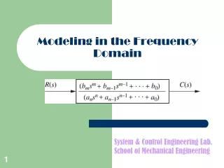
Why time-domain representation? • Two approaches are available for analysis and design of feedback control systems: • 1. Classical or frequency-domain • 2. Modern or time-domain, also known as a state-space approach • The first approach is based on converting a system’s differential equation to a transfer function. Thus generating a mathematical model of the system that algebraically relates a representation of the output to a representation of the input. • Replacing a differential equation with an algebraic equation not only simplifies the representation of individual subsystems but also simplifies modeling interconnected subsystems. • The main disadvantage of the classical approach is its limited applicability. It can be applied only a linear, time-invariant systems or systems that can be approximated as such. • On the other hand, the major advantage of this technique is that they rapidly provide stability and transient response information. That is, the effect of varying system parameters can be seen immediately until an acceptable design is met. Control Engineering Dr. Fadhil Aula Salahaddin University/College of Engineering Nov. 2018
Why time-domain representation? • With the presence of space exploration, modeling systems using classical approaches are inadequate. • The state-space approach is a unified method for modeling, analyzing, and designing a wide range of systems. • For example, state-space approach can be used to represent nonlinear systems that have backlash, saturation, and dead zone. Missile is one example that can well represented. • Many systems do not have just a single input and a single output. • Multiple-input, multiple-output, such as a vehicle with input direction and input velocity yielding an output direction and an output velocity, can be compactly represented in state-space with a model similar in for and complexity to that used for single-input, single-output systems. Control Engineering Dr. Fadhil Aula Salahaddin University/College of Engineering Nov. 2018
General State-Space Representation The general form of the state-space model is Control Engineering Dr. Fadhil Aula Salahaddin University/College of Engineering Nov. 2018
General State-Space Representation System variable: Any variable that responds to an input or initial conditions in a system. State variable: The smallest set of linearly independent system variables such that the values of the members of the set at time t0 along with known forcing functions completely determine the value of all system variable for all t t0. State vector: A vector whose elements are the state variables. State space: The n-dimensional space whose axes are the state variables. State equation: A set of n simultaneous, first-order differential equations with n variable, where the n variables to be solved are the state variables. Output equation: The algebraic equation that expresses the output variables of a system as linear combinations of the state variables and the inputs. Control Engineering Dr. Fadhil Aula Salahaddin University/College of Engineering Nov. 2018
General State-Space Representation For example, for a linear, time-invariant, second-order system with a single input v(t), the state equations could be as the following form: Where x1 and x2 are the state variables. If there is a single output, the equation could be as: B A C D Control Engineering Dr. Fadhil Aula Salahaddin University/College of Engineering Nov. 2018
State-Space Modeling Example: Find a state-space representation of the following electrical circuit if the output is the current through the resistor. Answer Control Engineering Dr. Fadhil Aula Salahaddin University/College of Engineering Nov. 2018
State-Space Modeling Example: Find the space-state representation of the following circuit for the output v0(t). Answer Control Engineering Dr. Fadhil Aula Salahaddin University/College of Engineering Nov. 2018
State-Space Modeling Example: Find the state-space representation for the following mechanical system. Answer Control Engineering Dr. Fadhil Aula Salahaddin University/College of Engineering Nov. 2018
State-Space Modeling Assignment: Chapter 4 Part One HW4.1 An RLC network is shown in the following figure. Define the state variables as x1 = iL and x2 = vC. Obtain the state differential equation and the output equation y = vL HW4.2 Two carts with negligible rolling friction are connected as shown in the following figure. An input force is u(t). The output is the position of cart 2, that is y(t)=q(t). Determine a state-space representation of the system. x Control Engineering Dr. Fadhil Aula Salahaddin University/College of Engineering Nov. 2018
Converting a Transfer Function to the State Space Consider the differential equation A convenient way to choose state variable is to choose the output, y(t), and its (n-1) derivatives as the state variables. This is called the phase-variable technique. Let the state variable denoted by xi; thus Control Engineering Dr. Fadhil Aula Salahaddin University/College of Engineering Nov. 2018
Converting a Transfer Function to the State Space Differentiating both sides, yields Note: the dot above the x signifies differentiation with respect to time. Control Engineering Dr. Fadhil Aula Salahaddin University/College of Engineering Nov. 2018
Converting a Transfer Function to the State Space Now, for both state variables and their derivatives: In matrix form, Control Engineering Dr. Fadhil Aula Salahaddin University/College of Engineering Nov. 2018
Converting a Transfer Function to the State Space Finally, since the solution to the differential equation is y(t) or x1, therefore the output equation in matrix for is: Control Engineering Dr. Fadhil Aula Salahaddin University/College of Engineering Nov. 2018
Converting a Transfer Function to the State Space Example: Find the state-space model of the transfer function for the following system block diagram. Answer Control Engineering Dr. Fadhil Aula Salahaddin University/College of Engineering Nov. 2018
Converting a Transfer Function to the State Space Example: Find the state-space representation of the transfer function shown in following block diagram. Answer Control Engineering Dr. Fadhil Aula Salahaddin University/College of Engineering Nov. 2018
Converting from State Space to a Transfer Function Given the state and output equations Taking the Laplace transform assuming zero initial conditions: Solving for X(s) or where I is the identity matrix. Substituting the above equation in the output equation of Y(s): Control Engineering Dr. Fadhil Aula Salahaddin University/College of Engineering Nov. 2018
Converting from State Space to a Transfer Function called a transfer function matrix. Since it releases the output vector, Y(s), to the input vector, U(s). However, if U(s)=U(s) and Y(s) = Y(s) are scalars, then the transfer function will be Control Engineering Dr. Fadhil Aula Salahaddin University/College of Engineering Nov. 2018
Converting from State Space to a Transfer Function Example: Given the system defined by the following state-space model, find the transfer function, T(s)=Y(s)/U(s), where U(s) is the input and Y(s) is the output. Answer Control Engineering Dr. Fadhil Aula Salahaddin University/College of Engineering Nov. 2018
State Space Model Assignments: Chapter 4 Part Two HW 4.3 Write the state equations and the output equation for the following transfer function. HW 4.4 Find the transfer function Y(s)/R(s) for the following system represented in state space model: Control Engineering Dr. Fadhil Aula Salahaddin University/College of Engineering Nov. 2018
End of Chapter Four! Control Engineering Dr. Fadhil Aula Salahaddin University/College of Engineering Nov. 2018