Download
1 / 28
280 likes | 459 Views
attila.racz@cern.ch on behalf of the CMS DAQ group. The F ast M erging M odule (FMM) for readout status processing in CMS DAQ Second and final prototype. LECC 2004, Boston USA. DAQ designed for 100 kHz maximum average trigger rate but…

E N D
attila.racz@cern.ch on behalf of the CMS DAQ group The Fast Merging Module (FMM) for readout status processing in CMS DAQSecond and final prototype LECC 2004, Boston USA
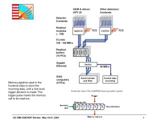
DAQ designed for 100 kHz maximum average trigger rate but… Higher instantaneous trigger rate is possible (Poisson) DAQ must not die by overflow if it happens! (and it will…) The TTS adapts the trigger pace with the DAQ processing capabilities sTTS for small buffer devices (fast response time, hardware parts) aTTS for large buffer devices (slow response time, software messages) Trigger Throttling System Attila RACZ / PH-CMD
TTS global view Attila RACZ / PH-CMD
The FMM receives the current state of n devices and process them to form a single state that can be used by the TTS to modify (or not) the trigger rate FMM and sTTS Attila RACZ / PH-CMD
Process (merges) the partition device states to form the detector partition status in a fast way (~100 ns) Monitors the dead time introduced by the partition devices Identification of (potential) pathologic FEDs Keeps a history memory of the state changes Allows to monitor the device states or playback for detailed analysis Generates input patterns for Trigger Control System Is also the output card for the aTTS FMM design requirements Attila RACZ / PH-CMD
Partition device state machine LV1A ratestill too high LV1A rate Fine Busy LV1A ratetoo high Warning Overflow Killing LV1A LV1A ratereduced Ready Out of sync LV1A ratereduced Resynch Reconnect Repair Error Discon- nected Attila RACZ / PH-CMD
States are provided on 4 bits: max transition rate = 40 MHz but we expect ~100 Hz ! 6 states defined for FEDs using 7 values 9 values “reserved” If a FED is in any reserved state, the FMM propagates a new state: illegal FEDs linked to an FMM can be in a different state: state priorities (decreasing order) are as follows: Disconnect Error Out_of_sync Busy Overflow Illegal Ready State encoding and priorities Attila RACZ / PH-CMD
24 connectors with LEDs, configurable as input or output at soldering time Allows to deal with 1 or 2 partitions and enable the card to be aTTS output Mask register a pathologic FED will not disturb the system once detected and identified Hardware dead-time monitors early detection of potential problem Cyclic history memory: only state transitions are recorded with time tag 2 MB/128 k transitions (16 bytes/transitions) Time tag resolution/range: 25 ns/40 bit (~7.6 hours) System clock at 80 MHz, Inputs sampled at 80 MHz but processed at 40 MHz History data can be pushed directly to host PC (“ala” FEDKIT) FPGA configuration files can be updated from PCI and on-board JTAG FMM features Attila RACZ / PH-CMD
Depending on the states Logical OR Arithmetic sum & threshold Can be modified on request thanks to the on-board FPGA Processing/Merging functions Attila RACZ / PH-CMD
FMM with 20 inputs max, 4 outputs: modulable in 20->1, 2x [10->1] (½) Double outputs are needed on the last FMM in the tree In this case, 8 FMMs per crate, one slot for reset distribution, 6 crates total FMMs in CMS Attila RACZ / PH-CMD
History capacity and BW • Each transition generates 80 bits (4 x 20) + 40 bits (time tag) or 16 bytes • 1MB of memory is 64K transitions • Worst case bandwidth on PCI backplane is 12MB/sec (with 8 FMMs per crate) • External memory of 2 MB is chosen Attila RACZ / PH-CMD
Output connectors PCI FPGA Altera PCI bus Core FPGA Xilinx Input connectors Config. PROM JTAG port ZBT RAM Block diagram Attila RACZ / PH-CMD
20 ƒReady 20x4 Inputs TTL DECODER E NCODER 2x4 Out TTL 20 ready 4 20 ƒBusy 2 X RJ45 to lvds drivers 20 20 x RJ45 from lvds receivers ƒDisconnect 20 busy 20 4 ƒError 20 out of sync 20 ƒOut of Sync 4 20 overflow 20 ƒOverflow reserved Test reg. Mask reg. Control I/F 40bit @ 40 MHz = 7.6 hours Time-tag 80 empty State Machine 80 40 Transition-detector Miss cnt. Busy (20) Overflow (20) write read Fifo 15 events full Dead-time Monitors 32 Add gen Direct write write Add/Data (32) Control I/F ZBTRAM interface Control (9+16) To Control I/F Add (19) Data (32) FPGA block diagram (20 inputs) Attila RACZ / PH-CMD
Compact PCI 6U double width form factor TTS connector allows standard RJ45 network cables At 40 MHz transition rate, LVDS drivers allows hundreds meter of cable length PCI control interface re-used from FRL design Same location of JTAG port enables the re-use of FRL testbed FMM implementation Attila RACZ / PH-CMD
Pin 1 -busy • Pin 2 +busy • Pin 3 -ready • Pin 4 +overflow warning • Pin 5 -overflow warning • Pin 6 + ready • Pin 7 -out of synch • Pin 8 +out of synch TTS connector • Standard RJ45 connector is used • Low cost, reliable, small footprint, high-density front panel • Socket with light-guides for bi-color LEDs Attila RACZ / PH-CMD
I/O block Attila RACZ / PH-CMD
I/O count: ~224 pins 24 TTS inputs/outputs: 96 pins Control I/F (32 A/D+misc): 48 pins Memory I/F (32D/20A): ~60 pins Misc. (Leds, prom, reset…) ~20 pins Logic gates: ~ 5000 FF (estimates based on proto1) Memory I/F: 300FF, 100 LUT Logic: ~750FF, ~875 LUT Monitors (raw counters): 3200FF, (4 states monitored) Pattern injection logic: ~700FF (comfortable…) Xilinx XC2VP7-5FG456 is selected: 248 I/Os, 10000 FF Core FPGA Attila RACZ / PH-CMD
2U wide , 6U height Compact PCI Same format as FRL 24 TTS I/O 8 status leds 2 push-buttons: reset and reprog Core FPGA Front Panel Attila RACZ / PH-CMD
Config For Virtex 2 X Eeprom Select JTAG 24 Drivers LVDS And 24 receivers LVDS RAM ZBT JTAG For Altera 10 X res_3V3 Sel Config. virtex CY2305 Osc. 80MHZ 16 X RSVD.. The eeprom for this altera is on the other Side. Reg. Reg. Reg. 8 X SMDleds with Light pipes PCB layout From FMM1 From FRL Attila RACZ / PH-CMD
Prototype picture Attila RACZ / PH-CMD
2 PCB produced and populated Register/memory tests passed Inputs/Outputs tested “one by one” at computer speed Wait after a “helper module” to stress all inputs at 40 MHz After… we enter production ! Production test software being debugged Status Attila RACZ / PH-CMD
End Attila RACZ / PH-CMD
Design the final prototype with PCI interface Compact PCI form factor (6 or 9U) See if 32 inputs is optimal Implement hardware monitoring engines What next after first prototype… Attila RACZ / PH-CMD
Validation of FMM concept 19-inch rack mounted 1U box A Xilinx Spartan II is the core FPGA Standard UTP5 Input connector running LVDS levels External SDRAM for history memory TINI module (WEB) used as control interface No deadtime monitor engine Core FPGA functions validated First prototype Attila RACZ / PH-CMD
First proto block diagram Output connectors LAN cable FPGA Xilinx Spartan II TINI module Input connectors Config. PROM JTAG port SDRAM Attila RACZ / PH-CMD
First proto FPGA block diagram 32 ƒReady 32x4 Inputs TTL DECODER E NCODER 2x4 Out TTL 32 ready 4 32 ƒBusy 2 X RJ45 to lvds drivers 32 32 X RJ45 from lvds receivers ƒDisconnect 32 busy 32 4 ƒError 32 out of sync 32 ƒOut of Sync 4 32 overflow 32 ƒOverflow reserved Mask reg. 40 MHz:256=6.4 us/tick Time-tag 128 empty State Machine 128 32 Transition-detector Miss cnt. write read Fifo 15 events full 32 Add gen Data (8) write TINI-interface SDRAM interface Add (20) Add (12) Data (32) Attila RACZ / PH-CMD
First prototype picture Attila RACZ / PH-CMD
History memory 16 MB/840 k transitions (20 bytes/transitions) Time tag resolution/range: 6.4 us/32 bit (~7.6 hours) Propagation time: 100 ns (4 clock cycles @ 25 ns) First prototype performances Attila RACZ / PH-CMD