Download
1 / 27
270 likes | 520 Views
Lecture 21 Overview. Counters Sequential logic design. Shift Register. Often, however, the bits will not arrive in parallel but in serial - one bit at a time Use a shift register Input is applied to first flip-flop and shifted along one at each clock event

E N D
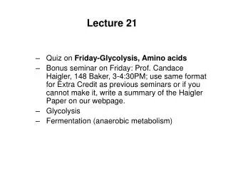
Lecture 21 Overview • Counters • Sequential logic design
Shift Register • Often, however, the bits will not arrive in parallel but in serial - one bit at a time • Use a shift register • Input is applied to first flip-flop and shifted along one at each clock event • This example is a 4-bit shift register • It accepts serial input, stores the last 4 bits in the sequence and makes them available as parallel output Parallel Output Serial Input http://www.eelab.usyd.edu.au/digital_tutorial/part2/register03.html
Digital counters: Ripple (Asynchronous) Counters Countersare sequential logic circuits that proceed through a well-defined sequence of states and then repeat. For a "divide-by-2" counter, simply connect the Q' output to the D input and feed an external clock signal in as the input: +'ve edge-triggered D flipflop Input Output Input Output For a "divide-by-4" counter, connect 2 flipflops together in a chain: Input Output Output Input • For a "divide-by-n" : connect 2n flipflops together. • Note that the FF outputs do not change at exactly the same time because of the propagation delay in each FF. • These counters are known as ripple or asynchronous counters.
Synchronous Counters • Connect all flip-flops to the same clock • All flipflops change state at the same time (synchronous) • A counter is a device which sequences through a fixed set of patterns • in this case, 1000, 0100, 0010, 0001 (if one of these patterns is the initial state, defined by set/reset) • Counts to n (n=number of flipflops) before repeating (ring counter) • Mobius (or Johnson) Counter • in this case, get 1000, 1100, 1110, 1111, 0111, 0011, 0001, 0000 • counts to 2*n before repeating http://www.eelab.usyd.edu.au/digital_tutorial/part2/register07.html
A B C D D Binary Counter A • We normally want to count in a more useful fashion: e.g. binary • This requires more combinationallogic between the flipflops • Need a rule for binary counting • "The least significant bit always changes" • "A bit changes state if all less significant bits are HIGH" • Can implement this with an XOR gate • Note Xxor1=X' So A+=Axor1, B+=BxorA, C+=CxorAB, D+=DxorABC
A B C D Binary Down Counter A D • How do you modify this circuit to count down? • The rule is • "The least significant bit always changes" • "A bit changes state if all less significant bits are LOW" • Note AXOR1=A' AXNOR0=A' So A+=Axor1, B+=BxnorA, C+=CxnorAB, D+=DxnorABC
ENDCBA LOAD CLK CLR RCO QDQCQBQA Pre-packaged Binary Counters • Counters can be bought pre-packaged: • e.g. a synchronous four-bit binary up/down-counter (e.g. DM74LS169A) • Standard component with many applications • Typical features: • Positive edge-triggered FFs with synchronous LOAD and CLEAR inputs • LOAD input allows parallel load of data from D, C, B, A • CLEAR input resets outputs to 0000 • EN input: must be asserted to enable counting • RCO: ripple-carry output used for cascading counters • High when counter is in its highest state 1111 • Implemented using an AND gate: RCO= QA·QB·QC·QD
Binary Counters • For an 8-bit synchronous binary up counter, cascade two 4-bit devices together • Connect RCO from the first to EN of the second
Offset Counters • Two types; for a "starting offset counter" use the synchronous LOAD input. • The counter counts like this: • 0110,0111,1000,1001,1010,1011,1100,1101,1111,0110,... Load value 0110 • For an "ending offset counter" use a pattern recognizer for the ending value • The counter counts like this: • 0000,0001,0010, ... , 1100,1101,0000, ....
Sequential Logic Summary • Fundamental building blocks of circuits with memory • latch and flipflop • R-S latch, R-S master-slave flipflop, D master-slave flipflop, edge-triggered D flipflop • Timing Methodologies • use of clocks • Basic registers • Storage register • Shift registers • pattern detectors • counters
Sequential Logic Design • Models for representing sequential circuits • Finite-state machines • Representation of memory (states) • Changes in state (transitions) • Design procedure • State diagrams • State transition table • Next state functions
CombinationalLogic External Inputs External Outputs State Inputs State Outputs Storage Elements Sequential Circuit Models:Abstraction of Circuit Elements • Break the sequential circuit down into all its different elements • External Inputs to combinational logic • External Outputs from combinational logic • Combinational logic • Storage elements • State Inputs to combinational logic • State Outputs from combinational logic
Abstraction of Circuit Elements • We often don’t have all of these • Special case: No External Inputs • E.g. Traffic light with no pedestrian control button CombinationalLogic External Outputs State Inputs State Outputs Storage Elements
Abstraction of State Elements • Special case: No external outputs • Output values correspond to state • E.g.: Counters with LD, ENABLE, and CLR inputs CombinationalLogic Inputs Outputs State Inputs State Outputs Storage Elements
Abstraction of State Elements • Special case: No explicit inputs or outputs • E.g.: Counters without LD, ENABLE, and CLR inputs CombinationalLogic Outputs State Outputs Storage Elements State Inputs
Clock Two Forms of Sequential Logic • Asynchronous sequential logic – state changes occur whenever state inputs change (elements may be simple wires or delay elements) • Hard to design due to race conditions, metastability. Rarely used. • ignore it from now on. • Synchronous sequential logic – state changes occur in step across all storage elements (using a periodic waveform - the clock) Asynchronous Synchronous
010 111 001 In = 1 In = 0 In = 0 100 110 In = 1 Finite State Machine Representations • A finite state machine model consists of: • State Nodes (Circles): determined by possible values in sequential storage elements • Transitions (Arrows): indicate a change of state; may or may not be associated with an input • Clock: controls when state can change by controlling storage elements. Not explicitly shown. • Sequential Logic • Sequences through a series of states • Based on a sequence of values of input signals • Clock period defines elements of sequence
OUT1 OUT2 OUT3 D Q D Q D Q IN CLK 110 100 010 101 111 000 001 011 Can Any Sequential System be Represented with a State Diagram? • What about a Shift Register? • Input value shownon transition arcs • Output values shownwithin state node
OUT1 OUT2 OUT3 D Q D Q D Q IN CLK 110 100 1 0 1 1 1 010 101 111 000 1 1 0 1 0 0 001 011 1 0 0 0 0 Can Any Sequential System be Represented with a State Diagram? • What about a Shift Register? • Input value shownon transition arcs • Output values shownwithin state node
010 011 001 000 100 3-bit up-counter 110 101 111 Counters are Simple Finite State Machines • Counters • Simply cycle through a well-defined state sequence. • Many types of counters: binary, BCD, Gray-code • 3-bit up-counter: 000, 001, 010, 011, 100, 101, 110, 111, 000, ... • 3-bit down-counter: 111, 110, 101, 100, 011, 010, 001, 000, 111, ... • No inputs once started, no explicit outputs
OUT1 OUT2 OUT3 D Q D Q D Q CLK "1" How Do We Turn a State Diagram into Logic? • For a 3-bit counter: • Need three flip-flops to hold state • Need combinational logic to compute next state • Clock signal controls when flip-flop memory can change • Wait long enough for combinational logic to compute new value before providing the next clock event State Storage Logic
FSM Design Procedure • Start with counters • Simple because the output is just the state • Simple because there is no choice of next state based on inputs • State diagram to state transition table • Tabular form of state diagram • Similar to a truth-table • State encoding: how do you represent the state in binary? • Decide on representation of states (e.g. traffic light green = what in binary?) • For counters it is simple: just its value • Implementation • Flip-flop for each state bit • Combinational logic based on state encoding
current state next state0 000 001 11 001 010 22 010 011 33 011 100 44 100 101 55 101 110 66 110 111 77 111 000 0 010 011 001 1 2 3 000 100 3-bit up-counter 4 0 110 101 111 7 6 5 FSM Design Procedure: State Diagram to Encoded State Transition Table • Transition table is just a tabular form of the state diagram • Shows all of the possible transitions • Like a truth-table (specify output for all input combinations) • Encoding of states: easy for counters – just use output value
current state next state0 000 001 11 001 010 22 010 011 33 011 100 44 100 101 55 101 110 66 110 111 77 111 000 0 010 011 001 000 100 3-bit up-counter 110 101 111 FSM Design Procedure: State Diagram to Encoded State Transition Table • Tabular form of state diagram • Shows all of the possible transistions • Like a truth-table (specify output for all input combinations) • Encoding of states: easy for counters – just use output value
C3 C3 1 1 0 0 0 1 1 0 1 1 0 0 1 0 0 1 C1 C1 C2 C2 C3 C2 C1 N3 N2 N10 0 0 0 0 10 0 1 0 1 00 1 0 0 1 10 1 1 1 0 01 0 0 1 0 11 0 1 1 1 01 1 0 1 1 11 1 1 0 0 0 N1 N2 N3 C3 C3C2 00 01 11 10 C1 0 0 0 0 1 1 1 0 1 1 C1 C2 Implementation current • Each state bit requires one D flip-flop • Combinational logic is needed to implement transition table next notation to show function representing input to D-FF N1 := C1' N2 := C1C2' + C1'C2 := C1 xor C2 N3 := C1C2C3' + C1'C3 + C2'C3 := C1C2C3' + (C1' + C2')C3 := C1C2C3' + (C1C2)'C3 := (C1C2) xor C3 Karnaugh maps for each output:
C3 C2 C1 N3 N2 N10 0 0 0 0 10 0 1 0 1 00 1 0 0 1 10 1 1 1 0 01 0 0 1 0 11 0 1 1 1 01 1 0 1 1 11 1 1 0 0 0C3 C2 C1 N3 N2 N10 0 0 0 0 10 0 1 0 1 00 1 0 0 1 10 1 1 1 0 01 0 0 1 0 11 0 1 1 1 01 1 0 1 1 11 1 1 0 0 0 Implementation • Each state bit requires one D flip-flop • Combinational logic is needed to implement transition table current next N1 := C1' N2 := C1C2' + C1'C2 := C1 xor C2 N3 := C1C2C3' + C1'C3 + C2'C3 := C1C2C3' + (C1' + C2')C3 := (C1C2) xor C3
In C1 C2 C3 N1 N2 N30 0 0 0 0 0 00 0 0 1 0 0 00 0 1 0 0 0 10 0 1 1 0 0 10 1 0 0 0 1 00 1 0 1 0 1 00 1 1 0 0 1 10 1 1 1 0 1 11 0 0 0 1 0 01 0 0 1 1 0 01 0 1 0 1 0 11 0 1 1 1 0 11 1 0 0 1 1 01 1 0 1 1 1 01 1 1 0 1 1 11 1 1 1 1 1 1In C1 C2 C3 N1 N2 N30 0 0 0 0 0 00 0 0 1 0 0 00 0 1 0 0 0 10 0 1 1 0 0 10 1 0 0 0 1 00 1 0 1 0 1 00 1 1 0 0 1 10 1 1 1 0 1 11 0 0 0 1 0 01 0 0 1 1 0 01 0 1 0 1 0 11 0 1 1 1 0 11 1 0 0 1 1 01 1 0 1 1 1 01 1 1 0 1 1 11 1 1 1 1 1 1 OUT1 OUT2 OUT3 D Q D Q D Q IN CLK 110 100 1 0 1 1 1 010 101 111 000 1 1 0 1 0 0 011 001 1 0 0 0 0 Another Example • Shift Register • In the counter, current state (only) determines next state • For a shift register Input + current state determines next state • Need an extra column in the transition table 3-bit shift register. Serial input, parallel output. N1 := In N2 := C1 N3 := C2 C1 N2 C2 N3 C3 N1