Download
1 / 36
360 likes | 375 Views
Explore the revolution happening in Japan with the design of the most useful and lifelike robot. This robot comes with a projector, WiFi, cellphone, speech recognition, and can speak Japanese. Read more about it now!

E N D
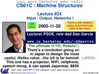
inst.eecs.berkeley.edu/~cs61cCS61C : Machine StructuresLecture #24Input / Output, Networks I2005-11-28 There is one handout today at the front and back of the room! CPStoday! Lecturer PSOE, new dad Dan Garcia www.cs.berkeley.edu/~ddgarcia The ultimate in I/O: Robots! There’s a revolution going onin Japan to design the mostuseful, lifelike robot…the US is far behind! This one has a projector, WiFi, cellphone, speech recog, & can speak Japanese. $85K news.3yen.com/2005-11-26/japanese-robot-gets-kissie-kissie/
Review • Manage memory to disk? Treat as cache • Included protection as bonus, now critical • Use Page Table of mappings for each uservs. tag/data in cache • TLB is cache of VirtualPhysical addr trans • Virtual Memory allows protected sharing of memory between processes • Spatial Locality means Working Set of Pages is all that must be in memory for process to run fairly well
Earlier Lectures Current Lectures Recall : 5 components of any Computer Keyboard, Mouse Computer Processor (active) Devices Memory (passive) (where programs, data live when running) Input Control (“brain”) Disk, Network Output Datapath (“brawn”) Display, Printer
Motivation for Input/Output • I/O is how humans interact with computers • I/O gives computers long-term memory. • I/O lets computers do amazing things: • Read pressure of synthetic hand and control synthetic arm and hand of fireman • Control propellers, fins, communicate in BOB (Breathable Observable Bubble) • Computer without I/O like a car without wheels; great technology, but won’t get you anywhere
I/O Device Examples and Speeds • I/O Speed: bytes transferred per second(from mouse to Gigabit LAN: 12.5-million-to-1) • Device Behavior Partner Data Rate (KBytes/s) Keyboard Input Human 0.01 Mouse Input Human 0.02 Voice output Output Human 5.00 Floppy disk Storage Machine 50.00 Laser Printer Output Human 100.00 Magnetic Disk Storage Machine 10,000.00 Wireless Network I or O Machine 10,000.00 Graphics Display Output Human 30,000.00 Wired LAN Network I or O Machine 125,000.00 When discussing transfer rates, use 10x
A way to connect many types of devices to the Proc-Mem Files APIs Operating System Proc Mem PCI Bus SCSI Bus cmd reg. data reg. What do we need to make I/O work? • A way to present them to user programs so they are useful • A way to control these devices, respond to them, and transfer data
Instruction Set Architecture for I/O • What must the processor do for I/O? • Input: reads a sequence of bytes • Output: writes a sequence of bytes • Some processors have special input and output instructions • Alternative model (used by MIPS): • Use loads for input, stores for output • Called “Memory Mapped Input/Output” • A portion of the address space dedicated to communication paths to Input or Output devices (no memory there)
cntrl reg. data reg. Memory Mapped I/O • Certain addresses are not regular memory • Instead, they correspond to registers in I/O devices address 0xFFFFFFFF 0xFFFF0000 0
Processor-I/O Speed Mismatch • 1GHz microprocessor can execute 1 billion load or store instructions per second, or 4,000,000 KB/s data rate • I/O devices data rates range from 0.01 KB/s to 125,000 KB/s • Input: device may not be ready to send data as fast as the processor loads it • Also, might be waiting for human to act • Output: device not be ready to accept data as fast as processor stores it • What to do?
Processor Checks Status before Acting • Path to device generally has 2 registers: • Control Register, says it’s OK to read/write (I/O ready) [think of a flagman on a road] • Data Register, contains data • Processor reads from Control Register in loop, waiting for device to set Ready bit in Control reg (0 1) to say its OK • Processor then loads from (input) or writes to (output) data register • Load from or Store into Data Register resets Ready bit (1 0) of Control Register
(IE) Receiver Control0xffff0000 (I.E.) Ready Unused (00...00) Receiver Data0xffff0004 Received Byte Unused (00...00) Transmitter Control 0xffff0008 (I.E.) Ready Unused (00...00) Transmitter Data0xffff000c Transmitted Byte Unused SPIM I/O Simulation • SPIM simulates 1 I/O device: memory-mapped terminal (keyboard + display) • Read from keyboard (receiver); 2 device regs • Writes to terminal (transmitter); 2 device regs
SPIM I/O • Control register rightmost bit (0): Ready • Receiver: Ready==1 means character in Data Register not yet been read; 1 0 when data is read from Data Reg • Transmitter: Ready==1 means transmitter is ready to accept a new character;0 Transmitter still busy writing last char • I.E. bit discussed later • Data register rightmost byte has data • Receiver: last char from keyboard; rest = 0 • Transmitter: when write rightmost byte, writes char to display
I/O Example • Input: Read from keyboard into $v0 lui $t0, 0xffff #ffff0000Waitloop: lw $t1, 0($t0) #control andi $t1,$t1,0x1 beq $t1,$zero, Waitloop lw $v0, 4($t0) #data • Output: Write to display from $a0 lui $t0, 0xffff #ffff0000Waitloop: lw $t1, 8($t0) #control andi $t1,$t1,0x1 beq $t1,$zero, Waitloopsw $a0, 12($t0) #data • Processor waiting for I/O called “Polling” • “Ready” bit from processor’s point of view!
Administrivia • Only 3 lectures to go (after this one)! :-( • Project 4 (Cache simulator) due friday • Performance contest rules up today • Deadline is Mon, 2005-12-12 @ 11:59pm, two weeks from today • HW4 and HW5 are done • Regrade requests are due by 2005-12-05 • Project 3 will be graded face-to-face, check web page for scheduling • Final: 2005-12-17 @ 12:30pm in 2050 VLSB!
Cost of Polling? • Assume for a processor with a 1GHz clock it takes 400 clock cycles for a polling operation (call polling routine, accessing the device, and returning). Determine % of processor time for polling • Mouse: polled 30 times/sec so as not to miss user movement • Floppy disk: transfers data in 2-Byte units and has a data rate of 50 KB/second. No data transfer can be missed. • Hard disk: transfers data in 16-Byte chunks and can transfer at 16 MB/second. Again, no transfer can be missed.
% Processor time to poll [p. 677 in book] Mouse Polling, Clocks/sec = 30 [polls/s] * 400 [clocks/poll] = 12K [clocks/s] • % Processor for polling: 12*103 [clocks/s] / 1*109 [clocks/s] = 0.0012% Polling mouse little impact on processor Frequency of Polling Floppy = 50 [KB/s] / 2 [B/poll] = 25K [polls/s] • Floppy Polling, Clocks/sec = 25K [polls/s] * 400 [clocks/poll] = 10M [clocks/s] • % Processor for polling: 10*106 [clocks/s] / 1*109 [clocks/s] = 1% OK if not too many I/O devices
% Processor time to poll hard disk Frequency of Polling Disk = 16 [MB/s] / 16 [B/poll] = 1M [polls/s] • Disk Polling, Clocks/sec= 1M [polls/s] * 400 [clocks/poll] = 400M [clocks/s] • % Processor for polling: 400*106 [clocks/s] / 1*109 [clocks/s] = 40% Unacceptable
What is the alternative to polling? • Wasteful to have processor spend most of its time “spin-waiting” for I/O to be ready • Would like an unplanned procedure call that would be invoked only when I/O device is ready • Solution: use exception mechanism to help I/O. Interruptprogram when I/O ready, return when done with data transfer
I/O Interrupt • An I/O interrupt is like overflow exceptions except: • An I/O interrupt is “asynchronous” • More information needs to be conveyed • An I/O interrupt is asynchronous with respect to instruction execution: • I/O interrupt is not associated with any instruction, but it can happen in the middle of any given instruction • I/O interrupt does not prevent any instruction from completion
Definitions for Clarification • Exception: signal marking that something “out of the ordinary” has happened and needs to be handled • Interrupt: asynchronous exception • Trap: synchronous exception • Note: Many systems folks say “interrupt” to mean what we mean when we say “exception”.
add sub and or (1) I/O interrupt user program (2) save PC (3) jump to interrupt service routine read store ... jr (5) interrupt service routine Interrupt-Driven Data Transfer Memory (4) perform transfer
(IE) Receiver Control0xffff0000 (I.E.) Ready Unused (00...00) Receiver Data0xffff0004 Received Byte Unused (00...00) Transmitter Control 0xffff0008 (I.E.) Ready Unused (00...00) Transmitter Data0xffff000c Transmitted Byte Unused SPIM I/O Simulation: Interrupt Driven I/O • I.E. stands for Interrupt Enable • Set Interrupt Enable bit to 1 have interrupt occur whenever Ready bit is set
Benefit of Interrupt-Driven I/O • Find the % of processor consumed if the hard disk is only active 5% of the time. Assuming 500 clock cycle overhead for each transfer, including interrupt: • Disk Interrupts/s = 16 MB/s / 16B/interrupt = 1M interrupts/s • Disk Interrupts, clocks/s = 1M interrupts/s * 500 clocks/interrupt = 500,000,000 clocks/s • % Processor for during transfer: 500*106 / 1*109 = 50% • Disk active 5% 5% * 50% 2.5% busy
Peer Instruction ABC 1: FFF 2: FFT 3: FTF 4: FTT 5: TFF 6: TFT 7: TTF 8: TTT • A faster CPU will result in faster I/O. • Hardware designers handle mouse input with interrupts since it is better than polling in almost all cases. • Low-level I/O is actually quite simple, as it’s really only reading and writing bytes.
Peer Instruction Answer Less sync data idle time Because mouse has low I/O rate polling often used Concurrency, device requirements vary! T R U E ABC 1: FFF 2: FFT 3: FTF 4: FTT 5: TFF 6: TFT 7: TTF 8: TTT • A faster CPU will result in faster I/O. • Hardware designers handle mouse input with interrupts since it is better than polling in almost all cases. • Low-level I/O is actually quite simple, as it’s really only reading and writing bytes. F A L S E F A L S E
Why Networks? • Originally sharing I/O devices between computers (e.g., printers) • Then Communicating between computers (e.g, file transfer protocol) • Then Communicating between people (e.g., email) • Then Communicating between networks of computers File sharing, WWW, …
How Big is the Network (2005)? ~30 ~525 ~6,400 (1999) ~50,000 ~9,000,000 ~217,000,000 ~318,000,000 Computers in 273 Soda in inst.cs.berkeley.edu in eecs&cs .berkeley.edu in berkeley.edu (100,000+?) in .edu in US(.net .com .edu .arpa .us .mil .org .gov) in the world Source: Internet Software Consortium: www.isc.org
Growth Rate Ethernet Bandwidth 1983 3 Mb/s 1990 10 Mb/s 1997 100 Mb/s 1999 1000 Mb/s 2006 10 Gig E (to come!) en.wikipedia.org/wiki/10_gigabit_ethernet
Memory bus PCI: Internal(Backplane) I/O bus CPU SCSI: External I/O bus PCI Interface Memory Ethernet Interface SCSI Interface (1 to 15 disks) Ethernet Local Area Network Buses in a PC: connect a few devices (2002) Bus - shared medium of communication that can connect to many devices. Hierarchy!! • Data rates (P4) • Memory: 400 MHz, 8 bytes 3.2 GB/s (peak) • PCI: 100 MHz, 8 bytes wide 0.8 GB/s (peak) • SCSI: “Ultra4” (160 MHz), “Wide” (2 bytes) 0.3 GB/s (peak) GigabitEthernet: 0.125 GB/s (peak)
Shared Node Node Node Node Crossbar Switch Node Node Node Shared vs. Switched Based Networks • Shared Media vs. Switched: in switched, pairs (“point-to-point” connections) communicate at same time; shared 1 at a time • Aggregate bandwidth (BW) in switched network ismany times shared: • point-to-point faster since no arbitration, simpler interface
Computer switch switch switch network interface What makes networks work? • links connecting switches to each other and to computers or devices • ability to name the components and to route packets of information - messages - from a source to a destination • Layering, protocols, and encapsulation as means of abstraction (61C big idea)
Typical Types of Networks • Local Area Network (LAN) Ethernet • Inside a building: Up to 1 km • (peak) Data Rate: 10 Mbits/sec, 100 Mbits /sec,1000 Mbits/sec (1.25, 12.5, 125 MBytes/s) • Run, installed by network administrators • Wide Area Network (WAN) • Across a continent (10km to 10000 km) • (peak) Data Rate: 1.5 Mb/s to 10000 Mb/s • Run, installed by telecommunications companies (Sprint, UUNet[MCI], AT&T) • Wireless Networks (LAN), ...
Example: Network Media Twisted Pair (“Cat 5”): Copper, 1mm thick, twisted to avoid antenna effect Light: 3 parts are cable, light source, light detector Total internal Fiber Optics Air reflection Transmitter Is L.E.D or Receiver Laser Diode – Photodiode light source Silica: glass orplastic; actually < 1/10 diameter of copper Cladding Buffer
“And in conclusion…” • I/O gives computers their 5 senses • I/O speed range is 12.5-million to one • Processor speed means must synchronize with I/O devices before use • Polling works, but expensive • processor repeatedly queries devices • Interrupts works, more complex • devices cause exception, OS runs and deal with the device • I/O control leads to Operating Systems • Integrated circuit (“Moore’s Law”) revolutionizing network switches as well as processors • Switch just a specialized computer • Trend from shared to switched networks to get faster links and scalable bandwidth