Download
1 / 36
360 likes | 473 Views
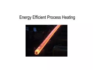
Energy Efficient Process Heating. Web Seminar By Kelly Kissock Ph.D., P.E. University of Dayton Industrial Assessment Center August 24, 2006. Heat Supply and Demand. Heat in Flue Gases. Furnace Heat Input. Stoichiometric Combustion Flame Temperature Available Heat. Combustion.

E N D
Energy Efficient Process Heating Web Seminar By Kelly Kissock Ph.D., P.E. University of Dayton Industrial Assessment Center August 24, 2006
Heat Supply and Demand Heat in Flue Gases Furnace Heat Input
Stoichiometric Combustion • Flame Temperature • Available Heat Combustion
Perfect (Stoichiometric) Combustion When fuel reacts with exactly the right amount of air, all of the carbon and hydrogen atoms combine with all of the oxygen to form carbon dioxide and water vapor. This is called “stoiciometric” combustion. CH4 + 2O2 CO2 +2H2O
Excess Air Most burners operated with more than stoichiometric air to guarantee that every fuel molecule finds an oxygen molecule. The quantity of air in “excess” to stoichiometeric air is called excess air. The quantity of excess air can be measured by measuring the amount of oxygen in the combustion gasses. Stoichiometric: CH4 + 2O2 CO2 +2H2O Excess Air: CH4 + 4O2 CO2 +2H2O + 2O2
Excess Air Combustion Products Analysis for a Typical Natural Gas
Excess Air Excess air dilutes the products of combustion, resulting in: 1) a lower flame temperature 2) less heat transfer from the combustion gasses to the load 3) more heat carried away in the exhaust gasses. CH4 + 4O2 CO2 +2H2O + 2O2
Flame (Combustion) Temperature Flame temperature affects heat transfer and temperature distribution within the heating system (furnace, oven etc.). • Flame (Combustion) Temp. (F)Condition • 4,450 NG, With 100% O2 • 3,750 NG, 900 F – 0% Excess Air • 3,545 NG, 900 F - 20% Excess Air • 3,460 NG, 70 F - O% Excess Air • 3,225 NG, 70 F - 15 % Excess Air • 2,750NG, 7.0:1 Air/Fuel Ratio
Effect of Oxygen Enhancement Flame Temperature for Natural Gas
Calculating Combustion Temperature • Combustion chamber • Stoichiometric combustion equation (for natural gas): • CH4 + 2 (O2 + 3.76 N2) CO2 + 2 H2O +7.52 N2 • Air/Fuel ratio for stoichiometric combustion: • AFs = 2 (O2 + 3.76 N2) / CH4 = 2 (32 + 3.76 28) / 16 = 17.2 • Combustion temperature (Tc) from energy balance: • Tc = Tca + LHV / [{1 + (1 + EA) AFs} Cpg]
Available Heat (Combustion Efficiency) • Available Heat = Available Heat = Fraction of energy not lost in exhaust gasses
Calculating Available Heat • Process heating system Percent available heat (h) from energy balance on system: h = [{1 + (1 + EA) AFs} Cpg (Tc – Tex)] / HHV mex Tex combustion chamber {Qout} mng + mca Tca
Air Flow • - Usually the largest loss in process heat. • - Air flow heat loss: • Boilers (250 F – 350 F): 20% • Aluminum furnace (1,400 F): 50% • Glass melter (2,500 F): 70%
Types of Air Flow • Combustion Air – needed to burn fuel • Ventilation Air – for moisture and volitile removal • Infiltration Air – undesirable; minimized by proper design and maintenance
Managing Combustion Air: Minimize Excess Air Optimum excess air for energy efficiency and pollution prevention: 10% (yields 2% O2 in comb gasses) Combustion temperature increases: Tc = Tca + LHV / [{1 + (1 + ECA) AFs} Cpg] Percent available heat (combustion efficiency) increases: h = [{1 + (1 + ECA) AFs} Cpg (Tc – Tex)] / HHV Example: • Aluminum melt furnace • 1,465 F exhaust gas temperature • Operates with 95% excess combustion air • Reducing excess air increases percent available heat from 39% to 60% • Energy use decreases by 35%
Managing Combustion Air: Preheating Recuperator schematic A recuperator transfers heat from exhaust gasses to inlet combustion air. Recuperator effectiveness (ε) relationship: ε = Q / [mca Cpa (Tex1 – Tca1)] = (Tca2 – Tca1) / (Tex1 – Tca1)
Managing Combustion Air: Preheating Combustion temperature increases: Tc = Tca + LHV / [{1 + (1 + ECA) AFs} Cpg] Percent available heat (combustion efficiency) increases: h = [{1 + (1 + ECA) AFs} Cpg (Tc – Tex)] / HHV Example: • Aluminum melt furnace • 2,500 F combustion temperature • 1,465 exhaust gas temperature • 40% effective recuperator increases comb. air temperature to 615 F • Increases combustion temperature to 3,010 F • Energy use decreases by 34%
Managing Combustion Air: Use Exhaust Air Exhaust gasses from ovens with high ventilation rates contain high O2 content, and can be redirected back to the burner as combustion air. Effective combustion temperature increases: Tc,eff = Tca + LHV / [{1 + (1 + EA) AFs} Cpg] Percent available heat (combustion efficiency) increases: h = [{1 + (1 + EA) AFs} Cpg (Tc,eff – Tex)] / HHV Example: • Curing oven at 250 F • 18% O2 in exhaust (about 660% excess air) • Using exhaust for combustion increases percent available heat from 64% to 67% • Energy use decreases by 4%
Managing Ventilation Air: Find Requirement • Industrial ovens must never exceed 25% of lower explosive limit (LEL) – National Fire Protection Agency Standard 86 This is achieved by: • using 10,000 cu. ft. of ventilation air per gallon of cured paint in continuous process. • using 380 cfm of ventilation air per gallon of cured substance in batch process.
Managing Ventilation Air: Minimize Ventilation air can be turned down manually through dampers to meet process demand or can be controlled with LEL sensors. Excess air decreases: Tc,eff = Tca + LHV / [{1 + (1 + EA) AFs} Cpg] Percent available heat (combustion efficiency) increases: h = [{1 + (1 + EA) AFs} Cpg (Tc,eff – Tex)] / HHV Example: • Curing oven with 141 F exhaust gasses • 3,700% excess air measured 3,470 cfm ventilation air • Ventilation air could be reduced to 45 cfm • Percent available heat would increase from 43% to 82% • Energy use would decrease by 47%
Managing Vent Air: Using Thermal Oxidizer Discharge Air Thermal oxidizers burn off volatile organic compounds in oven exhaust. Discharge air (usually around 300 F) can be redirected to oven. Effective combustion temperature increases: Tc,eff = Ta + LHV / [{1 + (1 + EA) AFs} Cpg] Percent available heat (combustion efficiency) increases: h = [{1 + (1 + EA) AFs} Cpg (Tc,eff – Tex)] / HHV Example: • Curing oven at 200 F internal temperature • 75% of air entering oven is ventilation air • Percent available heat would increase from 77% to 90% • Energy use would decrease by 14%
Managing Infiltration Ovens and furnaces are typically under negative pressure. Outside air will infiltrate through cracks, open doors, loose cracks, etc. through differential pressure and buoyancy effects. Vertical oven opening
Managing Infiltration: Move Opening to Floor Due to buoyancy effects, little cool air will infiltrate to a warm oven through its floor. Energy lost through infiltration (Qinf): Qinf = Vinfil A ρa Cpa (Texfil – Tinf) Qinf could be reduced by as much as 80%. Example: • Second story curing oven at 435 F temperature • Door area of 100 sq. ft. • Infiltration was measured to be 2,900 cfm • Energy use would decrease by 40% Horizontal oven opening
Managing Infiltration: Lower Openings Lowering openings decreases buoyancy effects between cool and warm air. New infiltration velocity (Vinf2) from Bernoulli’s Equation. Vinf2 = Vinf1 Energy saved (Qsav): Qsav = A Cpa [Vinf1ρa1 (Toven,1 – Tinf) – Vinf2ρa2 (Toven,2 – Tinf)] Example: • Curing oven at 450 F temperature • Door area of 8.5 sq. ft. • Infiltration was measured to be 2,250 cfm • Infiltration would reduce to about 2,000 cfm • Exfiltration temperature would decrease • Energy use would decrease by 28% Oven opening location before and after retrofit
Summary of Managing Air Flow • Savings opportunities for combustion air: • Minimize combustion air (35% savings) • Preheat combustion air (34% savings) • Use exhaust as combustion air (4% savings) • Savings opportunities for ventilation air: • Minimizing ventilation air (47% savings) • Using thermal oxidizer discharge air for ventilation (14% savings) • Savings opportunities for infiltration: • Move oven opening to floor (40% savings) • Lower oven openings (28% savings) • Savings calculations can be assisted by: • PHAST (www1.eere.energy.gov/industry/bestpractices/software.html) • HeatSim (www.engr.udayton.edu/udiac)
Heat Loss • Heat is lost through system walls by conduction, then convection and radiation. • Heat is lost from heated open tanks by convection, radiation, and evaporation.
Insulating Hot Surfaces • Heat lost (Q) from a surface: • Q = h A (Ts – Ta) + s A e (Ts4 – Ta4) e is ~0.9 for dark surface, ~0.1 for shiny surface Q = A (Tf– Ts) / Rshell convection component radiation component conduction
Insulating Hot Surfaces • Calculating convection coefficient (h) • Laminar air if: L3DT < 63 • Turbulent air if: L3DT > 63 • L = (length x width)1/2 for flat surfaces, L = diameter for cylindrical objects • Horizontal:hlam = 0.27 (DT / L) 0.25; htur = 0.22 (DT) 0.33 • Vertical:hlam = 0.29 (DT / L) 0.25; htur = 0.19 (DT) 0.33 • Horizontal:hlam = 0.27 (DT / L) 0.25; htur = 0.18 (DT) 0.33 • Vertical:hlam = 0.29 (DT / L) 0.25; htur = 0.19 (DT) 0.33 • Relations taken from ASHRAE Fundamentals Flat Surfaces{ Cylindrical Surfaces{
Covering Heated Tanks • Insulation floats can cover heated tanks to reduce convection and radiation heat transfer, and virtually eliminate evaporation. • Floats cover up to 79% of • liquid surface area. Energy balance on float: hfs (Tfs– Ta) + ε σ [Tfs4 – Ta4] = = (Tw – Tfs) / Rfloat HeatSim iterates values of float surface temperature until equation is balanced. Convection coefficient depends on surface temperature.
Covering Heated Tanks Convection heat loss (Qconv): • Qconv = h A (Tw – Ta) (h dependent on both water and air temperature) • Radiation heat loss (Qrad): • Qrad = A (Tw4 – Ta4) • Evaporation heat loss (Qconv): • Qevap = mw hfg (both values dependent on water and air temperature) • Total heat loss (Qtot): • Qtot = Qconv + Qrad + Qevap
Reducing Thermal Mass • Continuous Systems • Energy lost to conveyor (Qcvr) traveling at velocity (V): • Qcvr = V m Cpcvr (Tcvr2 – Tcvr1) Example: • Brazing oven at 1,900 F • Stainless steel conveyor at velocity 0.7 ft/min • Conveyor weighs 5 lbs/ft • Conveyor only loaded 30% of time • Conveyor is slowed to 0.3 ft/min when unloaded • 18,000 Btu/hr, or 40%, of conveyor energy saved
Reducing Thermal Mass • Batch Systems • Thermal mass in oven must heat to temperature during every batch cycle. • Thermal resistance (R1): • R1 = 1 / (h A) + dx / (2 k A) • R2 = R3 = R4 = R5 = R6 = R7 = R8 = dx / (k A) • Finite difference equations: • Ein – Eout = Estore • (TN – T) / RN – (T – TS) / RS = [dx A Cp (T’ – T)] / dt • T’ = dt (TN – T) / (RN dx A Cp) • – dt (T – TS) / (RS dx A Cp) + T Firebrick mass
Reducing Thermal Mass • Batch Systems Example – heat treat oven: • Heat treat oven with 100 sq. ft. floor • 8-inch thick firebrick layer • Oven is raised to 1,700 F, remains at temperature for 4 hours • Temperature decreases by 50 F every hour until temperature reaches 400 F Savings measure – reduce firebrick thickness: • Firebricks laid flat so new thickness is 4 inches • Energy savings is 235,000 Btu per cycle Temperature profile for 8-inch and 4-inch firebrick after cycle
Heat Loss Summary • Shell loss depends on insulation type and thickness. Insulate surfaces over 150 F. • Heat loss from heated open tanks dominated by evaporation. Cover tanks to minimize evaporation Minimize thermal mass of interior structure in batch processes with short cycle times Minimize thermal mass of conveyor in continuous processes. • Savings calculations assisted by: • PHAST (www1.eere.energy.gov/industry/bestpractices/software.html) • HeatSim (www.engr.udayton.edu/udiac)
Summary • Energy efficiency improved by: • Minimizing combustion air • Minimizing ventilation air • Minimizing infiltration air • Insulating surfaces over 150 F • Covering open heated tanks • Reducing mass of structure in batch processes • Reducing mass of conveyor in continuous processes • More information see our web site: • www.engr.udayton.edu/udiac