Download
1 / 38
380 likes | 515 Views
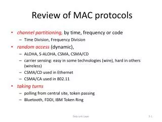
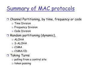
Summary of MAC protocols. What do you do with a shared media? Channel Partitioning, by time, frequency or code Time Division,Code Division, Frequency Division Random partitioning (dynamic), ALOHA, S-ALOHA, CSMA, CSMA/CD

E N D
Summary of MAC protocols • What do you do with a shared media? • Channel Partitioning, by time, frequency or code • Time Division,Code Division, Frequency Division • Random partitioning (dynamic), • ALOHA, S-ALOHA, CSMA, CSMA/CD • carrier sensing: easy in some technoligies (wire), hard in others (wireless) • CSMA/CD used in Ethernet • Taking Turns • polling from a central cite, token passing 5: DataLink Layer
LAN technologies Data link layer so far: • services, error detection/correction, multiple access Next: LAN technologies • addressing • Ethernet • hubs, bridges, switches • 802.11 • PPP • ATM 5: DataLink Layer
LAN Addresses and ARP 32-bit IP address: • network-layer address • used to get datagram to destination network (recall IP network definition) LAN (or MAC or physical) address: • used to get datagram from one interface to another physically-connected interface (same network) • 48 bit MAC address (for most LANs) burned in the adapter ROM 5: DataLink Layer
LAN Addresses and ARP Each adapter on LAN has unique LAN address 5: DataLink Layer
LAN Address (more) • MAC address allocation administered by IEEE • manufacturer buys portion of MAC address space (to assure uniqueness) • Analogy: (a) MAC address: like Social Security Number (b) IP address: like postal address • MAC flat address => portability • can move LAN card from one LAN to another • IP hierarchical address NOT portable • depends on network to which one attaches 5: DataLink Layer
223.1.1.1 223.1.2.1 E B A 223.1.1.2 223.1.2.9 223.1.1.4 223.1.2.2 223.1.3.27 223.1.1.3 223.1.3.2 223.1.3.1 Recall earlier routing discussion Starting at A, given IP datagram addressed to B: • look up net. address of B, find B on same net. as A • link layer send datagram to B inside link-layer frame frame source, dest address datagram source, dest address A’s IP addr B’s IP addr B’s MAC addr A’s MAC addr IP payload datagram frame 5: DataLink Layer
Question: how to determine MAC address of B given B’s IP address? ARP: Address Resolution Protocol • Each IP node (Host, Router) on LAN has ARP module, table • ARP Table: IP/MAC address mappings for some LAN nodes < IP address; MAC address; TTL> < ………………………….. > • TTL (Time To Live): time after which address mapping will be forgotten (typically 20 min) 5: DataLink Layer
ARP protocol • A knows B's IP address, wants to learn physical address of B • A broadcasts ARP query pkt, containing B's IP address • all machines on LAN receive ARP query • B receives ARP packet, replies to A with its (B's) physical layer address • A caches (saves) IP-to-physical address pairs until information becomes old (times out) • soft state: information that times out (goes away) unless refreshed 5: DataLink Layer
Routing to another LAN walkthrough: routing from A to B via R • In routing table at source Host, find router 111.111.111.110 • In ARP table at source, find MAC address E6-E9-00-17-BB-4B, etc A R B 5: DataLink Layer
A creates IP packet with source A, destination B • A uses ARP to get R’s physical layer address for 111.111.111.110 • A creates Ethernet frame with R's physical address as dest, Ethernet frame contains A-to-B IP datagram • A’s data link layer sends Ethernet frame • R’s data link layer receives Ethernet frame • R removes IP datagram from Ethernet frame, sees its destined to B • R uses ARP to get B’s physical layer address • R creates frame containing A-to-B IP datagram sends to B A R B 5: DataLink Layer
Ethernet “dominant” LAN technology: • cheap $20 for 100Mbs! • first wildey used LAN technology • Simpler, cheaper than token LANs and ATM • Kept up with speed race: 10, 100, 1000 Mbps Metcalfe’s Etheret sketch 5: DataLink Layer
Ethernet Frame Structure Sending adapter encapsulates IP datagram (or other network layer protocol packet) in Ethernet frame Preamble: • 7 bytes with pattern 10101010 followed by one byte with pattern 10101011 • used to synchronize receiver, sender clock rates 5: DataLink Layer
Ethernet Frame Structure (more) • Addresses: 6 bytes, frame is received by all adapters on a LAN and dropped if address does not match • Type: indicates the higher layer protocol, mostly IP but others may be supported such as Novell IPX and AppleTalk) • CRC: checked at receiver, if error is detected, the frame is simply dropped 5: DataLink Layer
Ethernet: uses CSMA/CD A: sense channel, if idle then { transmit and monitor the channel; If detect another transmission then { abort and send jam signal; update # collisions; delay as required by exponential backoff algorithm; goto A } else {done with the frame; set collisions to zero} } else {wait until ongoing transmission is over and goto A} 5: DataLink Layer
Ethernet’s CSMA/CD (more) Jam Signal: make sure all other transmitters are aware of collision; 48 bits; Exponential Backoff: • Goal: adapt retransmission attemtps to estimated current load • heavy load: random wait will be longer • first collision: choose K from {0,1}; delay is K x 512 bit transmission times • after second collision: choose K from {0,1,2,3}… • after jth collision: choose K from {0, ..., 2j-1} • after ten or more collisions, choose K from {0,1,2,3,4,…,1023} 5: DataLink Layer
Ethernet Technologies: 10Base2 • 10: 10Mbps; 2: under 200 meters max cable length • thin coaxial cable in a bus topology • repeaters used to connect up to multiple segments • repeater repeats bits it hears on one interface to its other interfaces: physical layer device only! 5: DataLink Layer
10BaseT and 100BaseT • 10/100 Mbps rate; latter called “fast ethernet” • T stands for Twisted Pair • Hub to which nodes are connected by twisted pair, thus “star topology” • CSMA/CD implemented at hub 5: DataLink Layer
10BaseT and 100BaseT (more) • Max distance from node to Hub is 100 meters • Hub can disconnect “jabbering” adapter • Hub can gather monitoring information, statistics for display to LAN administrators 5: DataLink Layer
Gbit Ethernet • use standard Ethernet frame format • allows for point-to-point links and shared broadcast channels • in shared mode, CSMA/CD is used; short distances between nodes to be efficient • uses hubs, called here “Buffered Distributors” • Full-Duplex at 1 Gbps for point-to-point links 5: DataLink Layer
Token Passing: IEEE802.5 standard • 4 Mbps • max token holding time: 10 ms, limiting frame length • SD, ED mark start, end of packet • AC: access control byte: • token bit: value 0 means token can be seized, value 1 means data follows FC • priority bits: priority of packet • reservation bits: station can write these bits to prevent stations with lower priority packet from seizing token after token becomes free 5: DataLink Layer
Token Passing: IEEE802.5 standard • FC: frame control used for monitoring and maintenance • source, destination address: 48 bit physical address, as in Ethernet • data: packet from network layer • checksum: CRC • FS: frame status: set by dest., read by sender • set to indicate destination up, frame copied OK from ring • DLC-level ACKing 5: DataLink Layer
Interconnecting LANs Q: Why not just one big LAN? • Limited amount of supportable traffic: on single LAN, all stations must share bandwidth • limited length: 802.3 specifies maximum cable length • large “collision domain” (can collide with many stations) • limited number of stations: 802.5 have token passing delays at each station 5: DataLink Layer
Hubs • Physical Layer devices: essentially repeaters operating at bit levels: repeat received bits on one interface to all other interfaces • Hubs can be arranged in a hierarchy (or multi-tier design), with backbone hub at its top 5: DataLink Layer
Hubs (more) • Each connected LAN referred to as LAN segment • Hubs do not isolate collision domains: node may collide with any node residing at any segment in LAN • Hub Advantages: • simple, inexpensive device • Multi-tier provides graceful degradation: portions of the LAN continue to operate if one hub malfunctions • extends maximum distance between node pairs (100m per Hub) 5: DataLink Layer
Hub limitations • single collision domain results in no increase in max throughput • multi-tier throughput same as single segment throughput • individual LAN restrictions pose limits on number of nodes in same collision domain and on total allowed geographical coverage • cannot connect different Ethernet types (e.g., 10BaseT and 100baseT) 5: DataLink Layer
Bridges • Link Layer devices: operate on Ethernet frames, examining frame header and selectively forwarding frame based on its destination • Bridge isolates collision domains since it buffers frames • When frame is to be forwarded on segment, bridge uses CSMA/CD to access segment and transmit 5: DataLink Layer
Bridges (more) • Bridge advantages: • Isolates collision domains resulting in higher total max throughput, and does not limit the number of nodes nor geographical coverage • Can connect different type Ethernet since it is a store and forward device • Transparent: no need for any change to hosts LAN adapters 5: DataLink Layer
Bridges: frame filtering, forwarding • bridges filter packets • same-LAN -segment frames not forwarded onto other LAN segments • forwarding: • how to know which LAN segment on which to forward frame? • looks like a routing problem (more shortly!) 5: DataLink Layer
Backbone Bridge 5: DataLink Layer
Interconnection Without Backbone • Not recommended for two reasons: - single point of failure at Computer Science hub - all traffic between EE and SE must path over CS segment 5: DataLink Layer
Bridge Filtering • bridges learn which hosts can be reached through which interfaces: maintain filtering tables • when frame received, bridge “learns” location of sender: incoming LAN segment • records sender location in filtering table • filtering table entry: • (Node LAN Address, Bridge Interface, Time Stamp) • stale entries in Filtering Table dropped (TTL can be 60 minutes) 5: DataLink Layer
Bridge Filtering • filtering procedure: ifdestination is on LAN on which frame was received then drop the frame else{ lookup filtering table if entry found for destination then forward the frame on interface indicated; else flood; /* forward on all but the interface on which the frame arrived*/ } 5: DataLink Layer
Bridge Learning: example Suppose C sends frame to D and D replies back with frame to C • C sends frame, bridge has no info about D, so floods to both LANs 3 and 2 • bridge notes that C is on port 1 • frame ignored on upper LAN • frame received by D 5: DataLink Layer
Bridge Learning: example • D generates reply to C, sends • bridge sees frame from D • bridge notes that D is on interface 2 • bridge knows C on interface 1, so selectively forwards frame out via interface 1 5: DataLink Layer
Disabled Bridges Spanning Tree • for increased reliability, desirable to have redundant, alternate paths from source to dest • with multiple simultaneous paths, cycles result - bridges may multiply and forward frame forever • solution: organize bridges in a spanning tree by disabling subset of interfaces 5: DataLink Layer
WWF Bridges vs. Routers • both store-and-forward devices • routers: network layer devices (examine network layer headers) • bridges are Link Layer devices • routers maintain routing tables, implement routing algorithms • bridges maintain filtering tables, implement filtering, learning and spanning tree algorithms 5: DataLink Layer
Routers vs. Bridges Bridges + and - + Bridge operation is simpler requiring less processing bandwidth - Topologies are restricted with bridges: a spanning tree must be built to avoid cycles - Bridges do not offer protection from broadcast storms (endless broadcasting by a host will be forwarded by a bridge) 5: DataLink Layer
Routers vs. Bridges Routers + and - + arbitrary topologies can be supported, cycling is limited by TTL counters (and good routing protocols) + provide firewall protection against broadcast storms - require IP address configuration (not plug and play) - require higher processing bandwidth • bridges do well in small (few hundred hosts) while routers used in large networks (thousands of hosts) 5: DataLink Layer