Download
1 / 31
310 likes | 646 Views
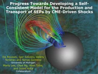
Progress Towards Developing a Self-Consistent Model for the Production and Transport of SEPs by CME-Driven Shocks. Ilia Roussev, Igor Sokolov, Valeriy Tenishev and Tamas Gombosi University of Michigan Marty Lee, Chee Ng, Allan Tylka, and Jozsef Kóta Collaborators. Objectives. Background:

E N D
Progress Towards Developing a Self-Consistent Model for the Production and Transport of SEPs by CME-Driven Shocks Ilia Roussev, Igor Sokolov, Valeriy Tenishev and Tamas Gombosi University of Michigan Marty Lee, Chee Ng, Allan Tylka, and Jozsef Kóta Collaborators
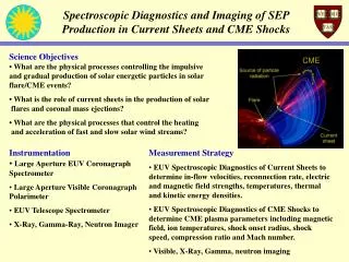
Objectives Background: • Solar eruptions play a major role in the Sun-Earth connection. • CME-driven shocks can accelerate charged particles to ultra-relativistic energies as the result of Fermi acceleration processes. • SEP events endanger human life in outer space and pose major hazards for spacecraft in the inner solar system. • For the success of the NASA’s exploration initiative (which envisions human and robotic exploration of the Moon and Mars) we need to develop a predictive capability of the radiation-environment conditions that will be experienced by human and robotic explorers. Near-Term Objectives: • Adopt a coordinated effort, which integrates theoretical knowledge from space physics, state-of-the-art numerical tools, and modern observational capabilities to better understand, predict, and mitigate the exposure of robotic and human explorers to space radiation. • Develop a self-consistent model based on the best theories that exist to study the production and transport of SEPs coupled to the dynamicsof realistic CME-driven turbulent shock waves in the heliosphere. Wisdom says:Vision without action is only day dreaming, while action without vision is merely passing time BUT vision with action can change the world!
SEP Danger to Human Life and Technology • Fact is: Astronauts in outer space are shielded by the “standard screen” with a stopping length of 0.54g/cm2 (2mm Aluminum). • Result is: SEPs with energies E>20MeV can penetrate the “standard screen” and thus endanger human life. • BUT: Spectrum of accelerated particles decays with energy. • So, the good news is: Particles of low energy (<20MeV) are less dangerous since they are efficiently screened. So are particles of higher energy (>100MeV) since their flux is small. • But, the bad news is: What to do about SEPs in the range 20-100MeV? • These particles are of great concern for astronauts safety. • Also, shielding of electronics becomes very difficult in this energy range. • More good news: Protons of energies >100 MeV usually reach the observer earlier than the practically dangerous ones, and so this can be used to alert astronauts about a radiation storm in progress. Wisdom says: Life is too short to skip dessert!
CME Shocks, DSA, etc. • Importance of DSA mechanism for SEP production is under debate: How do shock waves form? How strong are they near the Sun? • Very little is known about the dynamics of CME-driven shocks soon after the onset of the eruption (Alfvén speed may be too large near the Sun!) • In-situ measurements of shock wave properties near the Sun (and excited turbulence) are not yet available. • To address this issue requires that real magnetic data (and plasma density measurements) are incorporated into a global model of the solar corona. This is why numerical simulations are important! • It is necessary to couple a realistic CME-shock model with an adequate SEP model. • An adequate SEP model requires that a particle acceleration model be coupled with a realistic model of self-excited Alfvén turbulence and a model of particle transport in realistic IMF. • This approach bounds us to use coupled models… but, • Gives freedom to optimize the coupling so that each model is more exact and more efficient when coupled than when treated as a stand-alone model! Wisdom says: By believing passionately in something that still does not exist, we create it. The nonexistent is whatever we have not sufficiently desired…
List of Models Needed We need: • Global model of solar corona and inner heliosphere. • Realistic magnetic field in solar corona and inner heliosphere (1–216RS) needs to be involved. • Magnetic field observations should be incorporated. • This way one can get a more realistic Alfvén speed profile. • Magnetic connectivity problem is of crucial importance. • Model of CME initiation. • This is a challenge on its own! • There is no well accepted mechanism for triggering CMEs. • Again, magnetic field observations should be incorporated. • … and then, the field should be evolved in some magical way to achieve an eruption. • Once CME starts, the dynamical model of SC and heliosphere should properly describe evolution of strong shocks. • Kinetic model of SEP acceleration and transport • Realistic evolution of CME-driven shock waves is required. • First-order Fermi acceleration process produces SEPs from supra-thermals. • Self-consistent description of self-excited Alfvén turbulence and particle scattering at this turbulence is required. • For particle scattering upstream of shock, transversal diffusion should be taken into account as random displacement (~correlation length of turbulence) perpendicular to IMF.
Global Model of Solar Corona and Inner Heliosphere • We adopt the MHD model of Roussev et al. (2003), among others, to perform the coupling with a kinetic model of SEP acceleration. • MHD model is designed to reproduce the global structure of the solar corona and solar wind under realistic conditions. • Magnetic field in the model is split into a potential,B0, and a non-potential, B1, parts: B = B0+B1, where curl B0=0. • Observed line-of-sight photospheric magnetic field (MDI, WSO, etc.) is used to construct B0 using the PFSS method (Altschuler et al. 1977). • MHD solution in the model is evolved from a static, potential initial configuration to a steady-state, non-potential solution with a non-zero induced field, B1. • Solar wind is powered (heated and accelerated) by the energy interchange between the solar plasma and large-scale MHD turbulence, assuming that additional energy is stored in the “turbulent” internal degrees of freedom. • We adopt a physical approach in which the low value of specific heat ratio near the Sun is associated with those “turbulent” internal degrees of freedom. Wisdom says: Geocentric system is long dead (not egocentrism though!). Revise your stand point, broaden your scope of view, and new horizons discover you will!
Map of B0 (radial component) at the Sun on 2003 Oct 28 (n=90) Computed coronal magnetic field, B0+B1, at steady-state with solar wind Real Magnetic Data Drive MHD Simulations AR10486
Sheared-Arcade Models Flux Rope Models Variety of CME Models (Amari et al. 2000, 2003; Antiochos et al. 1999; Forbes & Isenberg 1991; Gibson & Low 1998; Kliem et al. 2004; Lin et al. 2001; Linker et al. 2001; Lynch et al. 2005; Manchester et al. 2003, 2004; Moore et al. 2001;Sturrock et al. 2001; Titov & Démoulin 1999; Tokman & Bellan 2002; Roussev et al. 2003, 2004)
Realistic CME Model: Are We Close to Have One? Summary on existing models: • There is no universal CME initiation mechanism. • No model is advanced enough to explain real events. • No observational evidence supports one class of models and rejects the other. • Existing CME models imply that at least some eruptions occur because coronal magnetic fields suffer a sudden loss of mechanical equilibrium or stability. • Various models differ in the means by which the loss of equilibrium is achieved. • Source of energy for solar eruptions comes from free energy stored in coronal electric currents. • Magnetic reconnection somehow disrupts the force balance of coronal fields and initiates CMEs. Presently, we do not have a realistic CME model at work! BUT, there are some CME models that are inspired by real events…. Wisdom says: You have not failed yet. You have found 10,000 ways that do not apply to real world (Sun).
Model of 1998 May 2 CME (Roussev et al. 2004) Basic elements • This numerical model incorporates magnetogram data from the Wilcox Solar Observatory and a loss-of-equilibrium mechanism to initiate the CME. • Eruption for the 1998 May 2 event is achieved by slowly evolving the boundary conditions for the magnetic field to account for: • Rotation of the main sunspot of AR8210, and • Flux cancellation nearby the rotating sunspot
CME-Shock Dynamics Key features of CME model • Excess magnetic energy needed to power the eruption is in good agreement with EIT data. • Eruption takes place in a multi-polar type magnetic field configuration. • Flux rope ejected during the eruption achieves a maximum speed in excess of 1,000 km/s — in good agreement with LASCO data. • CME drives a shock wave and interacts with a bi-modal solar wind. • Shock wave reaches a fast-mode Mach number in excess of 4 and compression ratio of about 3 at a distance of 5RS from the solar surface. Color code represents the flow speed in a meridional plane. Black lines visualize magnetic field lines. Grid structure is shown as the yellow mesh.
Field line position (in XZ-plane) at 13 instants of time (30 min apart) Number density distribution along the same field line at the same 13 instants From coupled CME-SEP Simulation of Sokolov et al. (2004) “Realistic” Evolution of Shock Wave
SEP-Turbulence Model • We need coupled model that describes the low-frequency plasma turbulence and SEP acceleration and transport. • For simplicity, let us use QL approximation to evaluate the growth rate of turbulent waves, and let describe particle motion in the diffusive approximation (for now). • Effects taken into account are: • Realistic evolution of shock wave front. • Advection of magnetic field in realistic solar wind model. • First-order Fermi acceleration for supra-thermals. • Self-consistent description of self-excited Alfvén turbulence and particle scattering at this turbulence. • Strength of this approach is that it enables us to quantify the particle acceleration and scattering by the self-excited Alfvén turbulence. • Self-excited turbulence is responsible for both the ion acceleration and shock wave structure. Wisdom says: As far as the laws of mathematics refer to reality, they are not certain. And, as far as they are certain, they do not refer to reality.
Quasi-1D Kinetic Equation • Diffusive limit (DL) is less exact but widely used, as here. • Consider as an example the kinetic equation (Parker 1966) governing the Diffuse-Shock-Acceleration (DSA) mechanism (THIS IS A 3D EQUATION!): • Here f is the isotropic part of the SEP distribution function, u is the bulk plasma velocity, D is the diffusion tensor. • Assume that diffusion only occurs along the IMF: • Assume that the IMF is frozen into the plasma • By introducing the Lagrangian coordinate along the IMF, s, the kinetic equation can be written for each IMF line separately: where is the plasma density. Note: Transformed equation depends on A SINGLE SPATIAL COORDINATE (quasi-1D). At the same time, the full 3D geometry of the IMF is preserved!
Field-Line-Advection Model for Particle Acceleration (FLAMPA) • Why are Lagrangian coordinates so effective? • SEPs move along the IMF line. • Lagrangian meshes (=fluid particles) move together with the frozen-in IMF. • One needs frequent dynamical coupling to MHD model to run the kinetic model of SEP production. • Trace Lagrangian meshes along the evolving IMF line. • Extract MHD parameters (u,,B, T) at these meshes. • This way the dynamical coefficients in the kinetic equation are obtained. • After each coupling, the solution of quasi-1D kinetic equation is advanced in time. • This approach works for the Skilling (1971) equation too (Kóta et al. 2005). • AND, also for the transport equation describing the Alfvén wave turbulence! Next step is: Compute the scalar diffusion coefficient, D, in a self-consistent manner by taking into account the enhanced level of Alfvén wave turbulence near the shock wave front due to the pitch-angle anisotropy of accelerated particles.
Coupled SEP-Turbulence Model [1] • We adopt a scattering integral of the form: • Distribution function is: • In DL, the particle anisotropy is given by: • Spatial diffusion coefficient is: • OR, in terms of integral by turbulent spectrum: where the resonant wave number kr is the inverse of the Larmor radius (=1/rB).
Coupled SEP-Turbulence Model [2] • In QL approximation, the growth rate of wave intensity is: • Here I+(k) and I–(k) are wave intensities of the outgoing and ingoing (with respect to the Sun) Alfvén waves, respectively, and I–(k) = 0.1 I+(k). • We assume Kolmogorov spectrum, i.e., I+(k) ~ k–5/3,as in Ng et al. (2003); • Kolmogorov spectrum is in agreement with the momentum dependence of the mean-free-path adopted by Zank et al. (2000) and Li et al. (2003). • Time-dependent changes in wave intensity are governed by the equation: • Self-generated Alfvén waves produced in the vicinity of shock-wave front have been demonstrated to have important consequences for SEP elemental abundance variations (Ng et al. 1999; Tylka et al. 1999) and evolution of SEP anisotropies (Reames et al. 2001). • Integrated approach adopted here allows us to improve the physical model of particle acceleration, which is coupled to the problem of turbulence excitation near the shock-wave front.
Summary and Future Work Summary: For the first time, realistic evolution of turbulence is coupled with the particle acceleration process! Future Work: • We presently work in the diffusive limit, but in future we will consider a more realistic SEP acceleration model that treats finite anisotropies of accelerated particles near the shock wave front. • We will extend the coupled SEP-turbulence model beyond the QL approximation. • Non-linear effects of wave-particle interactions are proven important (Ng et al. 2003). • We try to comply with existing models of interplanetary turbulence (by Matthaeus et al. and Goldstein et al.), but this work is in progress. • Unless we have a self-consistent model at work, we have too much freedom to satisfy any experimental data and, at the same time, too great uncertainty to believe the simulation results! • Although the conventional wisdom is that fluences at given decrease as R–2 while peak intensities fall of as R–3 (Reames and Ng 1998), this may not be generally true for any SEP event (structure of IMF, preceding CMEs and shocks, etc. matter a lot!). • Truly self-consistent model like the one outlined here should answer this and many other questions regarding the observed characteristics of SEP events! Wisdom says:The world belongs to those who DARE and DO!
Solicitation for Future Conference http://dezeeuwg4.engin.umich.edu/~ilr/ISROSES/
Description of FLAMPA • We start from diffusion equation for cosmic rays: (here f is the isotropic distribution function of particles) • Assume spatial diffusion only along given field line: • Use Lagrangian coordinates and assume that magnetic field is ideally frozen into plasma <=> we dictate that given magnetic field line consists of same Lagrangian meshes at any instant of time! Using the Lagrangian time derivative: and employing , we can reduce the CR diffusion equation, without any loss of generality, to ONE-DIMENSIONAL equation: • Diffusion coefficient is chosen as:
Coupling Between MHD Code and FLAMPA • We trace given field line by following the Lagrangian meshes (N~1500 ) it consists of. We solve N time equations of the kind: with velocity field u taken from MHD numerical solution, once every time step. • After previous coupling at time t1 we allow shock wave to pass distance ds between two neighboring Lagrangian meshes and at this time t2 we do next coupling between MHD code and FLAMPA. To do this, we extract values of B, temperature T, and density along traced field line and then send these to SEP code. • We update particle distribution function, f, from time t1 to t2 using the following discretization: • as advection with respect to momentum coordinate, using an explicit upwind scheme of 2nd order of accuracy; • as diffusion along spatial coordinate, using an implicit scheme. • Boundary condition at injection energy is:(we assume E-1 spectrum for suprathermal particles)
12RS 12RS 4RS 4RS Shock Evolution Cont. Shock compression ratio and fast-wave Mach number against time. Plasma beta (log-scale) and cosine of angle of upstream field to shock normal against time.
bright leading edge (pile-up behind shock) dark cavity region (flux rope) Density Structure and Field Geometry at t=1.1 hours.
SEP Event (3-4)RS! SEP Data for 1998 May 2 Event
12RS 4RS Shock Evolution Compression ratio of shock and proton cut-off energy predicted by diffusive-shock-acceleration theory. Interior labels along left axis indicate spectral index for non-relativistic particle flux used in theory: =0.5(X+2)/(X-1). Lower values of indicate harder spectrum
Time Sequence of Particle Spectra At R=12RS (before and after the shock wave passes) Time interval between two adjacent curves is 10 min. Dark red curve corresponds to t = 1.6 hrs (shock at R=12.2RS), whereas low-lying dark green curve refers to t = 0.27 hrs.
Summary of Results Model: • Our model incorporates magnetogram data from Wilcox Solar Observatory and loss-of-equilibrium mechanism to initiate solar eruption. • Eruption is achieved by slowly evolving boundary conditions for magnetic field to account for: • Sunspot rotation;and • Flux emergence and subsequent cancellation. Results: • Excess magnetic energy built in sheared field prior to eruption is 1.311x1031 ergs; • Flux rope ejected during eruption achieves maximum speed in excess of 1,040 km/s; • CME-driven shock reaches fast-mode Mach number in excess of 4 and compression ratio greater than 3 at distance of 4RS from solar surface.
Conclusions • CME-driven shock can develop close to Sun sufficiently strong to account for energetic solar protons up to 10 GeV! • SEP acceleration by diffuse-shock-acceleration mechanism, up to energies sufficient for penetrating into spacecraft, occurs in low corona at R~(3-12)RS and has relatively short time scale (~2 hrs.). • To simulate this properly, high-resolution MHD simulation should be coupled with kinetic equation for SEP diffusion along magnetic field lines, including Fermi type-A acceleration. Magnetic field line(s) motion should be traced using Lagrangian coordinates.