Download
1 / 73
730 likes | 871 Views
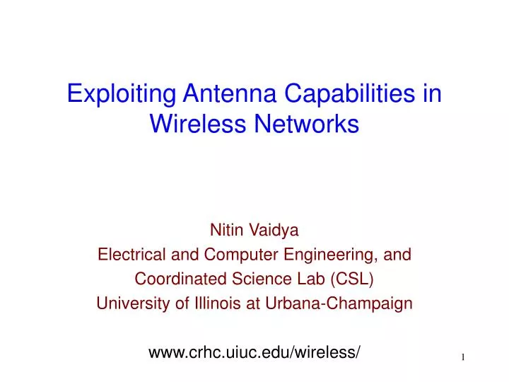
Exploiting Antenna Capabilities in Wireless Networks. Nitin Vaidya Electrical and Computer Engineering, and Coordinated Science Lab (CSL) University of Illinois at Urbana-Champaign www.crhc.uiuc.edu/wireless/. Wireless Capacity. Wireless capacity limited

E N D
Exploiting Antenna Capabilities in Wireless Networks Nitin Vaidya Electrical and Computer Engineering, and Coordinated Science Lab (CSL) University of Illinois at Urbana-Champaign www.crhc.uiuc.edu/wireless/
Wireless Capacity • Wireless capacity limited • In dense environments, performance suffers • How to improve performance?
Add Spectrum • Multi-channel versions of IEEE 802.11 • Practical limits on how much spectrum may be used
A B C D A B C D Power Controlto Improve Spatial Reuse
Improving Communication Locality • Local communication (among nearby nodes) uses less “space” • Allows spatial reuse among different flows • Improves per-flow capacity • Not always feasible: Application-dependent
infrastructure BS1 BS2 E A Z Ad hoc connectivity X Exploit Infrastructure • Infrastructure provides a “tunnel” through which packets can be forwarded • Can effectively improve locality of communication • Infrastructure access can become a bottleneck
Improving Per-Flow Capacity • Previous techniques are all useful,but have limitations • Dense networks likely to require further improvements in capacity • Exploit other forms of diversity • Mobility • Antennas
Antennas: Many Possibilities • Directional antennas • Diversity antennas • Reconfigurable antennas • …
Exploiting Antennas • Need protocol adaptations to exploit available antenna capabilities • Not sufficient to modify physical layer alone • Higher layer adaptation often necessary:medium access control (MAC) and routing
This TalkProtocols for Ad Hoc Networks usingDirectional Antennas Issues of interest • Medium access control • Neighbor discovery • Routing • Longer links, shorter routes • Longer times to failure • Broadcast-based discovery harder This talk • Deafness problem • MAC-Layer Anycasting
Outline • Preliminaries • A simple MAC protocol and the “deafness” problem • MAC-layer anycasting
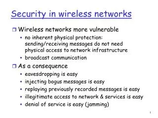
Ad Hoc Networks • Formed by wireless hosts which may be mobile • Without necessarily using a pre-existing infrastructure • Routes between nodes may potentially contain multiple hops Hidden terminals
Antenna Model • 2 Operation Modes: Omni & Directional • Directional mode typically has sidelobes • Not all antennas represented by this model
Antenna Model • Omni Mode: • Omni Gain = Go • Directional Mode: • Capable of beamforming in specified direction • Directional Gain = Gd (Gd > Go) Received poweraTransmit power*Gtx*Grx
A B D C Benefits of Directional AntennasGreater Received Power • Longer links may be formed • May lower Tx power, reducing interference to others
Benefits of Directional Antennas • Low gain in unwanted directions • Reduces interference to others • Example ….
Using Omni-directional Antennas • When C receives from D, B cannot transmit D A B C
D A B C Using Directional Antennas • C may receive from D, and simultaneously B may transmit to A
A B C Hidden Terminal Problem • Node B can communicate with A and C both • A and C cannot hear each other • When A transmits to B, C cannot detect the transmission using the carrier sense mechanism • If C transmits, collision may occur at node B
RTS (10) CTS (10) RTS/CTS Handshake in 802.11 • Sender sends Ready-to-Send (RTS) • Receiver responds with Clear-to-Send (CTS) • RTS and CTS announce the duration of the transfer • Nodes overhearing RTS/CTS keep quiet for that duration C 10 A B D 10
Outline • Preliminaries • A simple MAC protocol and the “deafness” problem • MAC-layer anycasting
Directional MAC(DMAC) • Idle node listens in omni-directional mode • Sender sends a directional RTS towards intended receiver • Receiver responds with directional CTS
Directional MAC(802.11 Variant) • DATA and ACK transmitted and received directionally • Nodes overhearing RTS or CTS remember not to transmit in corresponding directions • Overhearing nodes may transmit in other directions
A RTS B C D Directional MAC • C remembers not to transmit in A’s direction • C may transmit towards D
RTS Issues with DMAC • Hidden terminals due to asymmetry in gain • A does not get RTS/CTS from C/B B C A Data A’s RTS may interfere with C’s reception of DATA
A B RTS C Issues with DMAC: Deafness • Deafness: C does not know why no response from A • Cannot differentiate between collision, and busy node A • Conservative response is to “backoff” and try later D
A B RTS C Illustration • B initiates communication to A • While A is busy, C transmits RTS to A • No response from A • C waits a while, tries again • No response, C waits longer … • When A becomes free, C in wait mode • A become busy again, …. Repeat
RTS RTS CTS Data Backoff A B RTS ACK C RTS CTS Data Packet drop Illustration • B initiates communication to A • While A is busy, C transmits RTS to A • No response from A • C waits a while, tries again • No response, C waits longer … • When A becomes free, C in wait mode • A become busy again, …. Repeat
Impact of Deafness • Unnecessary transmissions of RTS • Increased packet drops • Increased delay and variance • Unfairness among flows
RTS RTS CTS Data Backoff A B RTS ACK C RTS CTS Data Packet drop Solutions to Deafness • Deafness since C does not know A is busy • Make C aware that A is busy • Require A to transmit a busy signal while receiving • Alternative: A transmits a “free” signal after it become idle
A B C RTS RTS CTS Data Backoff RTS ACK Backoff Tone RTS RTS CTS Data Solution: Tone DMAC • Nodes unable to communicate with A adapt backoff based on the “tone” from A • Think of it as “free-tone” as opposed to a “busy-tone” • A node need only use tone or data channel at any time, not both
Tone DMAC • Why a narrow-band tone? • Save bandwidth • Trade-off • Narrow-band signal prone to fading: Use long enough tone duration • Aliasing, since C cannot tell who transmitted a tone • Use multiple tones • One tone per node too expensive • Share tones
Tone DMAC • Node i transmit tone fifor durationti • fiand ti functions of the node identifier i fi = i mod F ti = i mod T
Tone DMAC • When a node, such as C in our example, hears a tone f for duration t, node C determines whether the tone could have been sent by its intended traget (node A in our example) • If C determines that A is the tone sender, C reduces its waiting time before next RTS • Aliasing can occur since multiple nodes can hash to the same tuple { f, t }
Backoff: Two flows to common receiver Backoff Counter for DMAC flows • Another possible improvement: Backoff Values Backoff Counter for ToneDMAC flows time
Packet Drops: Three flows, common receiver DMAC ToneDMAC time
UDP Throughput: Multiple multihop flows • ToneDMAC outperforms DMAC, ZeroToneDMAC ZeroToneDMAC = DMAC with only omnidirectional Backoff
Delay Performance: 2 flows, common Rx • Large fluctuation in DMAC packet delay Higher variance
TCP Throughput: Multiple multihop flows • RTT estimation of TCP better with ToneDMAC due to low delay variance
DMAC Summary • Deafness aggrevated by directional communication • “Free” tones, or other alternative mechanisms, appear useful to reduce degradation caused by deafness • Practicality issue: • Tone assignment • Fading Topic of ongoing research
Observation • Network layer typically selects one “optimal” route • MAC layer required to forward packet to next hop neighbor on this route • “Optimal” route selection based on a long-term view of the network • Independent of instantaneous channel conditions at each hop
Improvement ? • MAC layer aware of local link conditions • Congestion, channel fluctuations at smaller time scale • Power constraints for transmission • Virtual carrier sensing information (NAV in 802.11) • Exploit MAC layer awareness • Especially when using directional antennas • Forward packets based on combination of • Long-term directives of routing layer, and • Short-term knowledge at MAC layer
Our Proposal • Make forwarding decisions at the MAC layer • Utilize information already available to the MAC layer (as opposed to explicitly gathering feedback) • With DMAC, a node already knows that it cannot transmit in certain directions • Our approach can be combined with mechanisms that gather information explicitly
MAC-Layer Anycasting • Source often has multiple “good” routes to sink • Typically, one random downstream neighbor chosen • Supply multiple downstream neighbors to MAC layer • MAC layer chooses any one of the neighbors based on available information, and unicaststhe packet
Anycast module receives group of downstream neighbors Anycast group = {A, B, X} Anycast module forms anycast sequence (based on chosen policy) Seq. = {X, X, B, A, X, B, A} MAC layer attempts to transmit to “available” neighbors MAC-Layer Anycast Framework Network Layer Anycast Module MAC Layer Physical Layer