Download
1 / 17
230 likes | 831 Views
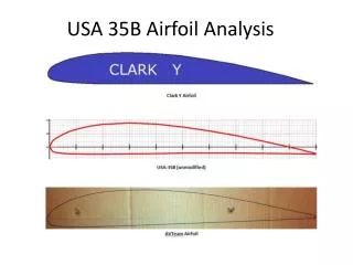
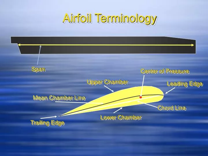
Airfoil Terminology. Span. Center of Pressure. Upper Chamber. Leading Edge. Mean Chamber Line. Chord Line. Lower Chamber. Trailing Edge. Types of Airfoils. Equal chamber on each side Each half mirror image of other Mean chamber line and chord line are coincidental

E N D
Airfoil Terminology Span Center of Pressure Upper Chamber Leading Edge Mean Chamber Line Chord Line Lower Chamber Trailing Edge
Types of Airfoils • Equal chamber on each side • Each half mirror image of other • Mean chamber line and chord line are coincidental • Produces zero lift at zero angle of attack • Constant center of pressure with varying angles of attack Symmetrical • Greater curvature above the chord line then below • Chord and chamber line are not coincidental • Produces useful lift even at negative angles of attack • Produces more lift at a given angle of attack than symmetrical • Better stall characteristics than symmetrical • Good lift to drag ratio • Limited to low relative wind velocity, <300 knots • Excessive center of pressure travel up to 20% of chord line Nonsymmetrical
Airfoil (Rotor Blade) Angles Angle of Incidence (pitch angle) Chord Line Tip Path Plane The mechanical angle between the chord line of the airfoil and the plane of rotation of the rotor (tip path plane). Changed by collective and cyclic feathering. Any change in the angle of incidence changes the angle of attack.
Airfoil (Rotor Blade) Angles Angle of Attack (aerodynamic angle) Chord Line Resultant RW Induced Flow Tip Path Plane The acute angle formed between the chord line of an airfoil and the resultant relative wind. As an aerodynamic angle the angle of attack can change with no apparent change in angle of incidence.
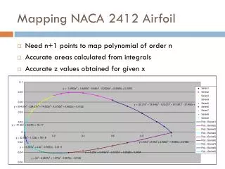
CL Max Stall 6° Angle of Attack 12° Angle of Attack 24° Angle of Attack 18° Angle of Attack
Enabling Learning Objective #5 From memory, the student will identify, by writing or selecting from a list, the principles of cyclic and collective feathering and the importance of rotary-wing flight, the significance of blade flapping and the significance of blade hunting and the forces involved with hunting IAW FM 1-203
Rotational Airflow (no forward movement) Tip Speed 700 FPS Circular movement of the rotor blades... ...Produces basic rotational relative wind. Maximum speed is at the tip of the blade and decreases uniformly to the hub Tip Speed 700 FPS
Feathering Feathering is the rotation of the blade about its span-wise axis • Feathering can be uniform throughout the rotor through collective inputs. • Feathering can be adjusted differentially through cyclic manipulation Lets look at some examples of feathering...
+ + + + Collective Feathering • The changing of the angle of incidence equally and in the same direction on all of the rotor blades simultaneously • Changes the angle of attack, which changes the coeffiecient of lift, which changes the overall lift of the rotor
Cyclic Feathering Differential change in angle of incidence around the rotor • Fore or aft cyclic movements result in changes in angle of incidence at the 3 and 9 o’clock positions around the rotor • Lateral cyclic movements result in the angle of incidence changing at the 12 and 6 o’clock positions around the rotor
- + Forward cyclic inputs A forward cyclic input increases pitch angle at the 9 o’clock position, and decreases it at the 3 o’clock position. Due to phase lag, the greatest upflap occurs at the 6 o’clock position. Total aerodynamic force inclines forward.
- + Aft cyclic inputs An aft cyclic input increases in the pitch of the blade at the 3 o’clock position while decreasing it at the 9 o’clock position. Due to phase lag, the highest upflap occurs at the 12 o’clock position. Total aerodynamic force inclines to the rear.
- + Lateral Cyclic Inputs Lateral cyclic inputs change the pitch angle at the 12 o’clock and 6 o’clock position. Due to phase lag those changes are manifested in the rotor system 90 degrees later. The resulting rotor attitude change causes the helicopter to move in the desired direction
Flapping Flapping is the up and down movement of the rotor blades about a flapping hinge (or flexible hub) • Blades flap in response to changes in lift caused by changes in velocity of the relative wind across the airfoil, or by cyclic feathering • No flapping occurs when the tip path plane is perpendicular to the mast Contributions • Helps prevent dyssemmetry of lift • Allows the rotor system to tilt in the desired direction in response to cyclic inputs
Lead and Lag Rotor blades in an articulated system lead ahead and lag behind their normal position in the rotor system Causes • Angle of attack changes and drag forces • Coriolis force, or the change in the relative center of gravity along the span of the blade
Blade CG Sequence when blade flaps up R 2 R 1 As the center of gravity moves inboard, a smaller radius of travel is produced. This causes the advancing blade to speed up or hunt. A vertical hinge pin (articulated rotor) allows the blade to sweep forward and absorbs stress that would otherwise be transmitted to the blade.