Download
1 / 11
140 likes | 808 Views
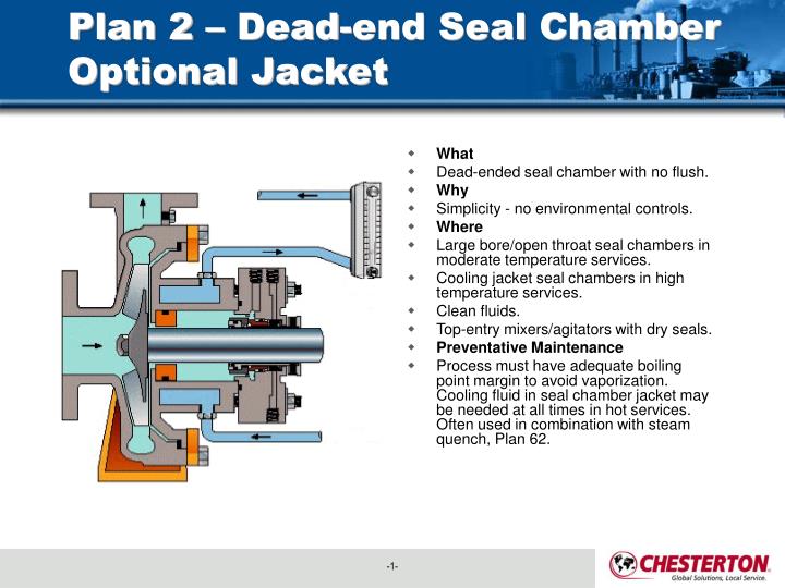
Plan 2 – Dead-end Seal Chamber Optional Jacket. What Dead-ended seal chamber with no flush. Why Simplicity - no environmental controls. Where Large bore/open throat seal chambers in moderate temperature services. Cooling jacket seal chambers in high temperature services. Clean fluids.

E N D
Plan 2 – Dead-end Seal Chamber Optional Jacket • What • Dead-ended seal chamber with no flush. • Why • Simplicity - no environmental controls. • Where • Large bore/open throat seal chambers in moderate temperature services. • Cooling jacket seal chambers in high temperature services. • Clean fluids. • Top-entry mixers/agitators with dry seals. • Preventative Maintenance • Process must have adequate boiling point margin to avoid vaporization. Cooling fluid in seal chamber jacket may be needed at all times in hot services. Often used in combination with steam quench, Plan 62.
Plan 11 - Discharge Recirculation • What • Seal flush from pump discharge through orifice. Default single seal flush plan. • Why • Seal chamber heat removal. • Seal chamber venting on horizontal pumps. • Increase seal chamber pressure and fluid vapor margin. • Where • General applications with clean fluids. Clean, non-polymerizing fluids. • Preventative Maintenance • Use an orifice with a minimum 0.125" (3 mm) diameter. Calculate flow rates to size orifice for adequate seal chamber flow. Increase boiling point margin with proper orifice and throat bushing sizing. Flush should be directed over seal faces with piping at 12 O'clock position. Typical failure mode is a clogged orifice - check temperatures at pipe ends.
Plan 12 or 31 – ALTERNATETraditional: Discharge Recirculation with Strainer or thru Cyclone • What • Seal chamber circulation created by Spiral Trac. Centrifuged solids are returned to pump suction. • Why • Solids removal from flush and seal chamber. • Seal chamber heat removal. • Where • Dirty or contaminated fluids, water with sand or pipe slag. • Non-polymerizing fluids. • Preventative Maintenance • Spiral Trac works best on solids with a specific gravity heavier than the process fluid. Seal chamber and application must be acceptable to flush-less Spiral Trac.
Plan 13 - Suction Recirculation • What • Recirculation from seal chamber to pump suction through orifice. Standard flush plan on vertical pumps. • Why • Continuous seal chamber venting on vertical pumps. Seal chamber heat removal. • Where • Vertical pumps. • Seal chamber pressure is greater than suction pressure. Moderate temperature fluids with moderate solids. Non-polymerizing fluids. • Preventative Maintenance • Vent piping loop prior to starting vertical pumps. • Use an orifice with a minimum 0.125" (3 mm) diameter. • Calculate flow rates to size orifice for adequate seal chamber flow. • Reduce seal chamber pressure with proper orifice and throat bushing sizing. • Typical failure mode is a clogged orifice - check temperatures at pipe ends.
Plan 14 – Continuous Venting –Vertical Pumps • What • Seal flush from pump discharge and recirculation to pump suction with orifices. Combination of Plan 11 and Plan 13. • Why • Continuous seal chamber venting on vertical pumps. • Seal chamber heat removal. • Increase seal chamber pressure and fluid vapor margin. • Where • Vertical pumps. • Clean, non-polymerizing fluids at moderate temperatures. • Preventative Maintenance • Use an orifice with a minimum 0.125" (3 mm) diameter. • Calculate flow rates to size orifice for adequate seal chamber flow. • Increase boiling point margin with proper orifice and throat bushing sizing. • Flush should be directed over seal faces. • Vent piping loop prior to starting vertical pumps. • Typical failure mode is a clogged orifice - check temperatures at pipe ends.
Plan 21 - Cooled Discharge Recirculation • What • Seal flush from pump discharge through orifice and cooler. Cooler in Plan 11 flush increases heat removal. • Why • Seal cooling. • Reduce fluid temperature to increase fluid vapor margin. • Reduce gasket damage. • Where • High temperature service, typically less than 350° F (177° C). Hot water over 180° F (80° C). Clean, non-polymerizing fluids. • Preventative Maintenance • Seal cooler and piping must have air vents at highest elevation - vent before starting. • Use an orifice with a minimum 1/8" (3 mm) diameter. • Calculate flow rates to size orifice for adequate seal chamber flow. • Increase boiling point margin with proper orifice and throat bushing sizing. • Regularly monitor device inlet and outlet temperatures for signs of clogging or fouling.
Plan 23 - Cooled Seal Recirculation • What • Seal flush from internal pumping device through cooler. Standard flush plan in hot water services. • Why • Efficient seal cooling with low cooler duty. Increase fluid vapor margin. Improve water lubricity. Preferred. Most cost effective. • Where • High temperature service, hot hydrocarbons. Boiler feed water and hot water over 180° F (80° C). Clean, non-polymerizing fluids. • Preventative Maintenance - Reference Appendix A • Seal cooler and piping must have air vents at highest elevation - vent before starting. • Seal chamber requires close clearance throat bushing to isolate process fluid. • Regularly monitor cooler inlet and outlet temperatures for signs of plugging or fouling. • Process fluids with iron should flow through magnetic separator before cooler.
Plan 32 - Clean Flush • What • Seal flush from an external clean source. • Why • Seal chamber heat removal. Process and solids removal from seal chamber. • Increase seal chamber pressure and fluid vapor margin. • Where • Dirty or contaminated fluids, raw water, condensate, chemical treatment. • High temperature service. • Polymerizing and/or oxidizing fluids. • Preventative Maintenance • Use throat bushing sized to hold pressure or maintain flow velocity. • To restrict dirty process fluid, regulate injection flow rate. • To increase fluid vapor margin, regulate injection pressure Injection fluid must be compatible with process fluid. • Regularly monitor control system for closed valves or signs of plugging
Plan 53 - Circulation with External Barrier Fluid Tank • What • Pressurized barrier fluid circulation through reservoir. • Fluid is circulated by a pumping ring in the dual seal assembly. • Why • Isolate process fluid. Zero process emissions. • Where • Used with dual pressurized seals ("double"). • Condensate • Dirty/abrasive or polymerizing fluids-Ash handling • Mixers/agitators and vacuum service. • Preventative Maintenance – • Piping loop must self-vent to reservoir located at highest elevation. • Pressurize reservoir at all times, maximum gas charge 150 - 200 psi (10 -14 bar). • Barrier fluid must be compatible with process. • Reservoir level gage indicates both inboard and outboard seal leakage.
Plan 54 - Circulation with External Barrier Fluid and Flowmeter • What • Pressurized barrier fluid circulation by external system. • Why • Isolate process fluid. Zero process emissions. Seal cannot induce circulation. • Where • Used with dual pressurized seals ("double"). • High vapor pressure fluids, condensate. • Dirty/abrasive or polymerizing fluids-Ash handling. • Mixers/agitators. • Preventative Maintenance • Piping loop must be fully vented before starting. • Circulating system must be pressurized and energized at all times. • Barrier fluid must be compatible with process. • Circulating system level gage indicates both inboard and outboard seal leakage.
Plan 62 - Quench • What • External quench on atmospheric side of seal. Quench fluids typically steam, nitrogen, or water. • Why • Prevent solids buildup on atmospheric side of seal. Prevent icing. • Where • Used with single seals. • Oxidizing fluids or fluids that coke, hot hydrocarbons. • Crystallizing fluids or fluids that salt out. • Caustic. Chemical treatment. • Cold fluids less than 32° F (0° C). • Preventative Maintenance • Quench inlet should be on top of gland with outlet/drain on bottom. • Quench pressure should be limited to 3 psi (0.2 bar) or less. Steam to 1 scfm. • Use throttle bushing on atmospheric side of seal to direct quench flow to seal drain. • Monitor regularly, checking for closed valves, blocked lines, and steam trap condition.