Download
1 / 23
230 likes | 707 Views
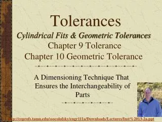
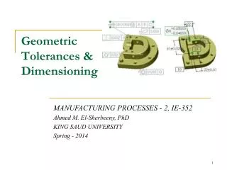
ANSI Y14.5-1994 Standard. This standard establishes uniform practices for defining and interpreting dimensions, and tolerances, and related requirements for use on engineering drawings.. The figures in this presentation are taken from Bruce Wilson'sDesign Dimensioning and Tolerancing.. Tools for Measuring Dimensions.

E N D
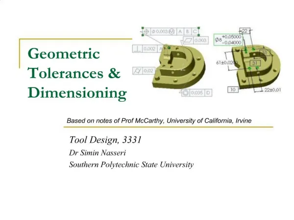
1. Geometric TolerancesJ. M. McCarthy Fall 2003
Overview of geometric tolerances
Form tolerances
Orientation tolerances
Location tolerances
Summary
3. Tools for Measuring Dimensions
4. Overview of Geometric Tolerances
5. Symbols for Geometric Tolerances
6. Feature Control Frame
7. Reference Frame
8. Order of Precedence
9. Using a Feature as a Datum
10. Material Conditions
11. Straightness of a Shaft
12. Straightness of a Hole
13. Straightness of a Center Plane
14. Flatness, Circularity and Cylindricity
15. Parallelism Tolerance
16. Perpendicularity
17. Perpendicular Shaft, Hole, and Center Plane
18. Angularity
19. Position Tolerance for a Hole
20. Material Condition Modifiers
21. Position Tolerance on a Hole Pattern
22. Datum Reference in a Composite Tolerance
23. Summary