Download
1 / 27
270 likes | 423 Views
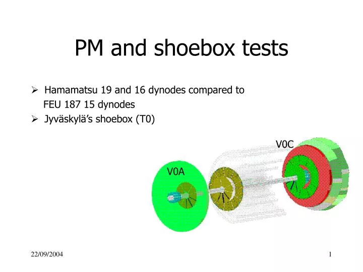
V0C. V0A. PM and shoebox tests. Hamamatsu 19 and 16 dynodes compared to FEU 187 15 dynodes Jyväskylä’s shoebox (T0). HT. 25 m. FI/FO. FI/FO. QDC. ped qdc. 5 m. PM. FA. start. anode. ped disc. THR1. TDC1. 25 m. thr1. optical fibers. gate. THR2. TDC2. thr2. 30 ns.

E N D
V0C V0A PM and shoebox tests • Hamamatsu 19 and 16 dynodes compared to FEU 187 15 dynodes • Jyväskylä’s shoebox (T0)
HT 25 m FI/FO FI/FO QDC pedqdc 5 m PM FA start anode peddisc THR1 TDC1 25 m thr1 optical fibers gate THR2 TDC2 thr2 30 ns THR3 TDC3 thr3 V0 counter THR4 TDC4 thr4 17 p.e./MIP Electronics for MIP measurements
18 14 15 20 19 21 FEU 187 gain
19 dynodes Hamamatsu 16 dynodes FEU 187 15 dynodes Hamamatsu and FEU 187 gain
16 17 15 Hamamatsu / FEU 187 • MIP measurement at equal gain • 17 p.e. for the most probable charge • 12 pC / 60 mV • charge = MIP / 4 for Hamamatsu PMT • charge = MIP / 2 for Russian PMT • time (Ham.) = 1.5 time (FEU 187) • a threshold at 2 charge (98%) • - MIP / 2 mV for Hamamatsu (30 mV) • - 0 for FEU 187 • Hamamatsu will be selected for V0
17 p.e. 2 > 0 mV FEU 187 MIP amplitude > 60 mV 2 > 30 mV Ham. dynamics: 3 mV-3 V time versus discriminator threshold
17 p.e. 2 MIP efficiency Maximum efficiency MIP versus discriminator threshold
H6153-70 = R5946 + HV divider (+) • PMT and divider in in a common cylinder • makes the mounting easy • simplifies the mechanics
HT 25 m A10/A25 FI/FO QDC pedqdc 5 m PM start A1 anode peddisc THR1 TDC1 25 m thr1 optical fibers THR2 TDC2 gate thr2 30 ns shoebox THR3 TDC3 thr3 V0 counter THR4 TDC4 thr4 17 p.e./MIP CFD TDC4 thr Electronics for tests with the schoebox
Measurement with the shoebox • 16 dynodes Hamamatsu tube • Charge distributions as a function of - high voltage: 1400, 1600, 1750, 1800, 2000, 2200 - amplification factor: 1, 10, 25 • Time resolution with amplification 10 and threshold / constant fraction discriminators as a function of - high voltage: 1400, 1600, 1800, 2000, 2200 • Extraction of the time resolution values still to be carried out
Without shoebox HT= 1400 V, A=1 HT= 1400 V, A=1 HT= 1400 V, A=25 HT= 1400 V, A=10 Charge distributions at 1400 V from 16 dynodes Hamamatsu PMT
100 ohms To TRD wake-up G=3.2 To T0 FEE threshold disri. and QDC 50 ohms G=3.2 G=3.2 Anode PM signal 50 ohms To T0 FEE CFD T0 schoebox as described in TDR
Signal amplitude 30 mV – 1. V (50 mV – 1. V) Signal amplitude Signal charge Signal charge 6 pC - >200 pC 6 pC - >200 pC 9.5 mV – 300 mV (10 pC - >200 pC) (10 pC - >200 pC) (16 mV – 300 mV) Signal amplitude 3 mV – 3 V (5 mV – 5 V) 100 ohms To TRD wake-up G=3.2 G=3.2 To V0 FEE threshold disri. 50 ohms G=3.2 OR NINO Anode PM (0.1 – 2 pC) 2 ns shaper signal 50 ohms G=1 To V0 FEE QDC Signal charge Signal amplitude 0.6 pC - 600 pC 3 mV – 3 V (1 pC - 1000 pC) (5 mV – 5 V) V0 pulse treatment
15/10/2004 CIU PCB prototype
16/11/2004 Tests in progress
Conclusion • Choice of the Hamamatsu PMT 16 dynodes • gain = 3 106 at 2000 V (FEU = 3 105) • charge resolution = MIP/4 (FEU = MIP/2) • time resolution (MIP = 17 p.e.) < 1 ns at 1750 V (FEU # 1.4 ns) • Choice of the T0 shoebox with an amplification of 10 • direct signal to QDC • amplified (clamped) signal to discriminator
Present programme • Order of: • VME crate: 15/12/2004 • 70 systems H6153-70 (PM5946-70 + HT divider): 15/12/2004 - delivery: 10 (06/2005), 20 (07/2005), 20 (08/2005), 20 (09/2005) • scintillator BC404: 15/12/2004 • shifting fibers: 15/12/2004 • optical fibers: 15/12/2004 • Sector ’’0’’: • available: 03/2005 • tested: 04/2005 • design review: 04/2005 • Sectors ’’1’’ - ’’7’’ + V0C box + V0C fiber cables • available: 11/2005 • tested: 12/2005 • PM characterisation: • gain curves: 12/2005 • V0C ready end of 2005 • V0A ready in June 2006 • Electronics R&D: follows the time-table (TDR) • CIU prototype tested: end 2004
Hamamatsu Hamamatsu / FEU 187 Spectral response
Recommendation for the HV sign 1) The R5505-70 and the R5946-70 are for +HV operation. > > We usually recommend +HV operation for all of the Fine Mesh PMTs. The > reason is as follows: > > Basically, there is no difference in PMT itself between -HV model and > +HV model. When a fine mesh PMT is operated at -HV, it sometimes > generates large noises. This is due to discharge between electrodes > (former stages of dynodes), the bulb and supporting materials outside. > Fine mesh PMT has proximity configuration, the electrodes are set > close to the window and the bulb. When -HV is used, potential of these > electrodes become -HV. There could be large potential difference > somewhere around window. In case of +HV operation, as cathode is > grounded, there is less potential difference between electrodes, the > bulb and supporting materials. Therefore noise becomes less. We would > like to recommend +HV operation for all customers.
1. Here is the anode dark current stability data of the R5946 (1.5« Fine Mesh PMT). The horizontal axis is operating time and the verticalaxis is the anode dark current recorded by ampere meter and recorder(10 mV = 100 nA). The upper data was measured at -HV operation and thelower one was measured at +HV operation. The PMT was supported by itssocket, and there was nothing around the PMT bulbs. Spike noisesappeared at -HV operation. However,when it was used at +HV operation,the noise became less.
Waveform of the pulse 2. We checked the waveform of the R5505(1 inch Fine Mesh PMT) and thefollowing is its data. Blue curve is at -HV operation and pink one isat +HV operation. Although the overshoot was rather seen at +HV, it'snot so much. Therefore, we would like to recommend +HV operation.
27 16 29 17 28 15 Hamamatsu / FEU 187 comparison 60 mV pulse