Download
1 / 1
10 likes | 155 Views
IPAC 2013, Shanghai. Neutrino Factory. Measure input particle x,x ’, y,y ’, t, t’=E/Pz input emittance in. Measure output particle x,x ’, y,y ’, t, t’=E/Pz output emittance out. COOLING CHANNEL. Preliminary. M. Rayner, U Genève. DATA. MC. LH2 System. RAL.

E N D
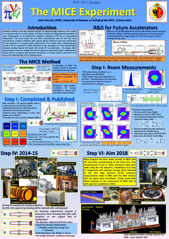
IPAC 2013, Shanghai Neutrino Factory Measure input particle x,x’,y,y’, t, t’=E/Pz input emittance in Measure output particle x,x’,y,y’, t, t’=E/Pz output emittance out COOLING CHANNEL Preliminary M. Rayner, U Genève DATA MC LH2 System RAL Tracker 1 Completed: Inner view shown The MICE Experiment Alain Blondel, DPNC, University of Geneva, on behalf of the MICE Collaboration Introduction R&D for Future Accelerators Ionization Cooling is the only practical solution to preparing high brilliance muon beams for a neutrino factory or muon collider. The Muon Ionization Cooling Experiment (MICE) is under development at the Rutherford Appleton Laboratory (UK) by an international collaboration. The muon beam line has been commissioned and, for the first time, measurements of beam emittance with particle physics detectors have been performed. The full apparatus is currently under construction. First results with a liquid-hydrogen absorber will be produced in 2015; followed by the operation of a full representative ionization cooling channel cell which will include RF re-acceleration. The design offers opportunities to observe cooling with various absorbers and several optics configurations. Results will be compared with detailed simulations of cooling channel performance to ensure full understanding of the cooling process. MICE is a critical R&D experiment on the path toward neutrino factories and muon colliders. With the growing importance of neutrino physics and the possibility of a light Higgs (115-130 GeV), physics could be moving this way soon! In such machines, the initial chain of capture, bunching, phase rotation, and cooling rely on complex beam dynamics and technology. Muon cooling g high intensity n factory, high luminosity m collider The MICE Method Step I: Beam Measurements A schematic of MICE: the cooling channel & upstream and downstream detectors • TOF system allows excellent p, m, e separation up to 300 MeV/c • CKOV studies show good separation of particles g identification at low momenta • KL (calorimeter) used to measure p contamination in m beams Measure parameters particle by particle: accumulate ~105 muons gD[(ein – eout/ein)] = 10-3 Challenges: high gradient (>12MV/m) RF cavities embedded in strong (>2T) solenoidal magnetic fields. Preliminary 1. Time-of-Flight (6,200) beam: muons in blue 2. Transverse beam profile at TOF1 Right: Pion fraction in m beam < 1-2% Step I: Completed & Published • MICE recorded > 106 particle triggers with p, e, and m beams to meet Step 1 goals: • Calibrated detectors & understood beam • Generated reproducible m beams • Analysed beam composition, m rates, data quality, and emittance • Took data for each e-p optics setting in MICE 3.4 m path from TOF0 to TOF1: drifts & quads • Emittance measurement: • ID muons with time-of-flight • Measure x,y and t at TOF0, TOF1 • Use momentum-dependent transfer matrices to map m path • Assume straight line path, estimate pzand iterate to calculate true pz • Determine trace space at TOF0 & TOF1. • - measured pz & transfer matrix M(pz) p (MeV/c) A schematic of the Step I MICE beam line Time-of-flight (TOF) for 300 MeV/c p beam e (mm) • Everything works well! • Muon rate ~120 in 2ms spill @ 0.4Hz • TOF resolutions: • st = 55, 53, and 50 ps and sx,y~1 cm • First measurement of emittance made using TOFs. 5. Transverse trace space for (6 mm, 200 MeV/c) m- beam. Non-linear effects at edges MICE m beam optics (en,pz) Step IV: 2014-15 Step VI: Aim 2018 Spectrometer Solenoid 1 Focus Coil Major progress has been made recently in MICE with the successful commissioning of the beam line. First measurements of the m beam emittance have been made using the TOF detectors. Installation of all Step IV components will continue through 2014, followed by the first high precision (0.1%) emittance measurements made in MICE with the fiber trackers (470 mm space point resolution). Finally, world-wide effort continues on the construction of MICE Step VI with a goal of completion in 2018. RF Amplifier: Daresbury Spectrometer Solenoid 2 Absorber Windows UK US: Berkeley, DOE UK, US Diffuser UK Mississippi Be Windows Tracker 2 RF Couplers - Berkeley Berkeley Coupling Coil – Harbin China RF Cavities Berkeley EMR: UGeneve All Step IV components nearing completion. By 2014, this engineering drawing will be replaced with a photograph! Spectrometer Solenoid & Tracker • An extensive experimental program is planned for 2013, including data taken with variations on the original Step IV configuration. • No absorber: alignment & beam optics • Liquid H2 absorber (full/empty) • Multiple scattering, Energy Loss • g COOLING • Solid absorbers: LiH, Plastic, C, Al, Cu • LiH wedge absorber: emittance exchange RFCC Module Absorber Fully engineered MICE Cooling Channel Cell Well… some ‘details’ left!