Download
1 / 17
200 likes | 446 Views
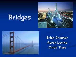
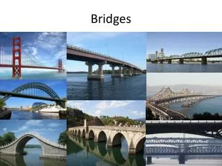
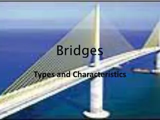
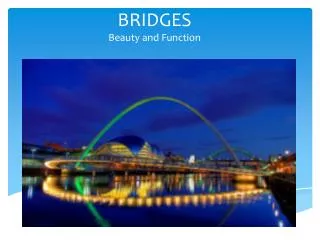
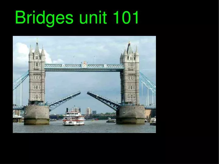
Bridges unit 101. Types of bridge. Over the Humber! the largest single span suspension bridge in the World. The first Iron bridge at Ironbridge SHROPSHIRE. Longest Bridge. 1. Lake pontchartrain .

E N D
Over the Humber! the largest single span suspension bridge in the World
Longest Bridge 1. Lake pontchartrain Pontchartrain lake road, or road, which consists of two parallel bridges that are of the longest bridges in the world and the total length. [2] in parallel with these pontchartrain bridges crossing the lake in southern Louisiana. The longest of the two bridges is 23.87 miles (38.42 km) long. Bridges supported by more than 9000 Huddling concrete. Bascule bridges feature extends over the channel 8 nautical miles (13 kilometers) south of the North Shore. The southern end of the road is in Metairie, Louisiana, a suburb of New Orleans. North ultimately is Mandeville, Louisiana.
A girder bridge is perhaps the most common and most basic bridge. A log across a creek is an example of a girder bridge in its simplest form. In modern steel girder bridges, the two most common girders are I-beam girders and box-girders. If we look at the cross section of an I-beam girder we can immediately understand why it is called an I-beam (illustration #1.) The cross section of the girder takes the shape of the capital letter I. The vertical plate in the middle is known as the web, and the top and bottom plates are referred to as flanges. To explain why the I shape is an efficient shape for a girder is a long and difficult task so we won't attempt that here.
A box girder is much the same as an I-beam girder except that, obviously, it takes the shape of a box. The typical box girder has two webs and two flanges (illustration #2.) However, in some cases there are more than two webs, creating a multiple chamber box girder. Other examples of simple girders include pi girders, named for their likeness to the mathematical symbol for pi, and T shaped girders. Since the majority of girder bridges these days are built with box or I-beam girders we will skip the specifics of these rarer cases. Now that we know the basic physical differences between box girders and I-beam girders, let's look at the advantages and disadvantages of each. An I-beam is very simple to design and build and works very well in most cases. However, if the bridge contains any curves, the beams become subject to twisting forces, also known as torque. The added second web in a box girder adds stability and increases resistance to twisting forces. This makes the box girder the ideal choice for bridges with any significant curve in them. Box girders, being more stable are also able to span greater distances and are often used for longer spans, where I-beams would not be sufficiently strong or stable. However, the design and fabrication of box girders is more difficult than that of I beams. For example, in order to weld the inside seams of a box girder, a human or welding robot must be able to operate inside the box girder.
Truss Like the girder bridges, there are both simple and continuous trusses. The small size of individual parts of a truss make it the ideal bridge for places where large parts or sections cannot be shipped or where large cranes and heavy equipment cannot be used during erection. Because the truss is a hollow skeletal structure, the roadway may pass over (illustration #2) or even through (illustration #1) the structure allowing for clearance below the bridge often not possible with other bridge types.
Trusses are also classified by the basic design used. The most representative trusses are the Warren truss, the Pratt truss, and the Howe truss. The Warren truss is perhaps the most common truss for both simple and continuous trusses. For smaller spans, no vertical members are used lending the structure a simple look (illustration #1.) For longer spans vertical members are added providing extra strength (illustration #2.) Warren trusses are typically used in spans of between 50-100m.
The Pratt truss (illustration #3) is identified by its diagonal members which, except for the very end ones, all slant down and in toward the center of the span. Except for those diagonal members near the center, all the diagonal members are subject to tension forces only while the shorter vertical members handle the compressive forces. This allows for thinner diagonal members resulting in a more economic design.
The Howe truss (illustration #4) is the opposite of the Pratt truss. The diagonal members face in the opposite direction and handle compressive forces. This makes it very uneconomic design for steel bridges and its use is rarely seen
Rigid Frame Rigid frame bridges are sometimes also known as Rahmen bridges. In a standard girder bridge, the girder and the piers are separate structures. However, a rigid frame bridge is one in which the piers and girder are one solid structure. The cross sections of the beams in a rigid frame bridge are usually I shaped or box shaped. Design calculations for rigid frame bridges are more difficult than those of simple girder bridges. The junction of the pier and the girder can be difficult to fabricate and requires accuracy and attention to detail. Though there are many possible shapes, the styles used almost exclusively these days are the pi-shaped frame, the batter post frame, and the V shaped frame.
The batter post rigid frame bridge is particularly well suited for river and valley crossings because piers tilted at an angle can straddle the crossing more effectively without requiring the construction of foundations in the middle of the river or piers in deep parts of a valley (illustration #1). V shaped frames make effective use of foundations. Each V-shaped pier provides two supports to the girder, reducing the number of foundations and creating a less cluttered profile (illustration #3.)
Pi shaped rigid frame structures are used frequently as the piers and supports for inner city highways. The frame supports the raised highway and at the same time allows traffic to run directly under the bridge (illustration #2