Download
1 / 33
340 likes | 1.06k Views
Irreversible Flow from Turbine Exit to Condenser . P M V Subbarao Professor Mechanical Engineering Department I I T Delhi. Irreversibilities due to Closed Cycle Policy …. The Last Stage of LP Turbine. First Stage of A Turbine : Governing Stage.

E N D
Irreversible Flow from Turbine Exit to Condenser P M V Subbarao Professor Mechanical Engineering Department I I T Delhi Irreversibilities due to Closed Cycle Policy …..
First Stage of A Turbine : Governing Stage • A governing stage is the first stage in a turbine with nozzle steam distribution. • The principal design feature of a governing stage is that its degree of partiality changes with variations of flow rate through the turbine. • The nozzles of a governing stages are combined into groups, each of them being supplied with steam from a separate governing valve. • A governing stage is separated by a spacious chamber from the subsequent non-controlled stages. • Governing stages may be of a single-row or two-row type. • Single row impulse governing stage is employed for an enthalpy drop of 80-120 kJ/kg. • Two row governing stages are used when enthalpy drop is high, 100 – 250 kJ/kg.
Selection of Enthalpy Drop & Type of Governing stage • The enthalpy drop & type of governing stages are selected by considering the probable effect of the governing stage on the design and efficiency of the turbine. • Higher the number of governing stages, lower will be the number of other stages. • A high enthalpy drop in governing stage ensures a lower temperature of steam in its chamber and permits application of less expensive materials. • In high capacity steam turbines, a single-row governing stages are preferred, since the advantages of elevated enthalpy drop are justified economically. • The efficiency of governing stages,
Steam Path in Non-Controlled Stages • Estimate approximate mass flow rate of steam by assuming an overall turbine internal efficiency of 0.85. • Calculate flow through the condenser, using optimum of number of FWHs. (Using Cycle Calculations). • Calculate Modified Efficiency of Low volume and intermediate volume stages. • For a group of stages between two successive FWHs. • Average density is calculated as
The efficiency of groups of very high volume stages: • While designing the steam path, it is essential to consider the pressure losses in the following: • Pressure loss in reheater: 0.1 prh. • Pressure loss in connecting pipes between turbine cylinders:0.2ppipe.
4Ia 4Is 4IIa 4IIs 4IIIa 4IIIs 4IVa 4IVs 4Va 4Vs 4VIa 4VIs Internal Reheating due to Irreversibilities 3 Governing group Group 1 Macro available enthalpy: Group 2 Group 3 T Group 4 Group 5 Micro available enthalpy: 4s s
Macro available enthalpy: Micro available enthalpy: Reheat Factor:
4Ia 4Is 4IIa 4IIs 4IIIa 4IIIs 4IVa 4IVs 4Va 4Vs 4VIIa 4VIa 4VIIIa 4IXa 4VIs Internal Reheating due to Irreversibilities : HP 22.33 MPa,3379.0 3 Governing stage 15.74 MPa,3303.0 k J/kg Pho=5 % Stage 1 13.77 MPa, 3269.0 k J/kg Pho=19.5% Stage 2 12.12 MPa, 3236.5.0 k J/kg Stage 3 Pho=21% 10.56 MPa, 3203.8 k J/kg T Stage 4 Pho=22% 9.2 MPa, 3171.0 k J/kg Stage 5 Pho=23.5% 7.94 MPa, 3140.4 k J/kg Stage 6 Pho=25% 6.9 MPa, 3104.9 k J/kg Stage 7 5.95 MPa, 3070.9 k J/kg Pho=30% Stage 8 4s Pho=32% s Pho=35% 5.17 MPa, 3036.7 k J/kg
Definition of Efficiency Relative blade efficiency is calculated as: • Internal Relative Efficiency is calculated as:
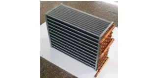
LP Turbine Exhaust System • In a condensing steam turbine, the low-pressure exhaust hood, consisting of a diffuser and a collector or volute!, connects the last stage turbine and the condenser. • The function of the hood is to transfer the turbine leaving kinetic energy to potential energy while guiding the flow from the turbine exit plane to the condenser. • Most of exhaust hoods discharge towards the downward condenser. • Flow inside the hood therefore must turn about 90 deg from the axial direction to the radial direction before exhausting into the condenser. • The 90-deg turning results in vortical flow in the upper half part of the collector and also high losses. • The exhaust hood is one of the few steam turbine components that has the considerable aerodynamic losses. • It is a challenge for engineers to operate a hood with high pressure recovery and low total pressure loss in a compact axial length.
Steam Turbine Exhaust Size Selection • The steam leaving the last stage of a condensing steam turbine can carry considerably useful power to the condenser as kinetic energy. • The turbine performance analysis needs to identify an exhaust area for a particular load that provides a balance between exhaust loss and capital investment in turbine equipment.
Exhaust Losses • Exhaust losses are losses which occur between last stage of turbine and condenser. • Exhaust losses made up of four components: • Actual leaving losses • Gross hood loss • Annulus restriction loss • Turn up loss
Residual velocity loss Steam leaving the last stage of the turbine has certain velocity, which represent the amount of kinetic energy that cannot be imparted to the turbine shaft and thus it is wasted Exhaust end loss Exhaust end loss occur between the last stage of low pressure turbine and condenser inlet. 2. Exhaust loss depends on the absolute steam velocity. Turbine Exhaust end loss = Expansion-line -end point - Used energy at end point.
Typical exhaust loss curve showing distribution of component loss Annulus restriction loss Total Exhaust Loss SP.Volume Annulus velocity (m/s) Turn-up loss Condenser flow rate Gross hood loss Annulus area Actual leaving loss Percentage of Moisture at the Expansion line end point 50 40 Exhaust Loss, kJ/kg of dry flow 30 20 10 0 120 150 180 240 300 360 Annulus Velocity (m/s)
Performance Analysis of Power Plant Condensers P M V Subbarao Professor Mechanical Engineering Department I I T Delhi A Device Which makes Power Plant A True Cycle.. A Device Which set the limit on minimum cycle pressure…..
Dead Steam Water ready to take Rebirth A Device to Convert Dead Steam into Live Water
Steam Condenser • Steam condenser is a closed space into which steam exits the turbine and is forced to give up its latent heat of vaporization. • It is a necessary component of a steam power plant because of two reasons. • It converts dead steam into live feed water. • It lowers the cost of supply of cleaning and treating of working fluid. • It is far easier to pump a liquid than a steam. • It increases the efficiency of the cycle by allowing the plant to operate on largest possible temperature difference between source and sink. • The steam’s latent heat of condensation is passed to the water flowing through the tubes of condenser. • After steam condenses, the saturated water continues to transfer heat to cooling water as it falls to the bottom of the condenser called, hotwell. • The difference between saturation temperature corresponding to condenser vaccum and temperature of condensate in hotwell is called condensate depression.