Download
1 / 14
140 likes | 204 Views
Proposal on Threshold Corrections for RC Filters. Eva Barbara Holzer f or the BLM team LHC MPP CERN, July 17, 2010. History (April 2010): Injection of higher intensity. RC filter for the monitors requested by the injection team factor 25 (all are external monitors;)

E N D
Proposal on Threshold Corrections for RC Filters Eva Barbara Holzer for the BLM team LHC MPP CERN, July 17, 2010
History (April 2010): Injection of higher intensity • RC filter for the monitors requested by the injection team factor 25 (all are external monitors;) • Maximum current will be reduced by a factor of 8.3 by RC filter and additional factor of 3 with (future) thresholds • Factor of ~10 between signal on external and internal monitors • For moment the threshold values not changed! • For all other energies the thresholds are now too high • A quench could occur • New thresholds to be calculated asap • All these monitors set to maskable • Estimate: Quench of magnet by outside shower if injection intensity 2e13
New Thresholds after filter installation • Allow injection losses 450 GeV thresholds have to be adapted to the shape of instantaneous (delta) losses. Well defined procedure, which was already done for different magnets (not discussed here). • All other energies: adapt thresholds to ‘cancel’ the effect of the filter • Definition of cancel: same amount of loss leads to beam abort with the same time delay • Correction factor for thresholds depends on the time evolution of the beam loss • 100% correction for all possible loss scenarios is not possible need to decide on a reasonable loss evolution
Investigate Dependence on Loss Evolution • Filter response approximated by exponentially decaying signal (rise time = zero). • For bigger filters (rise time 0.3ms) this is not a good approximation • For the filter in question the rise time is between 0.12 ms to 0.2ms (to be confirmed). If confirmed, the thresholds of the first 3 integration times should be reduced further accordingly. • Analytical calculation • Filter response folded with loss evolution • Integrated signal
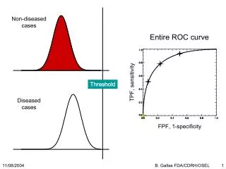
Proton loss distributions Protons lost in a.u. δ(t - 0) δ(t - integration_time) Time normalized to integration time
Loss distributions: correction effect gets stronger • δ(t - 0) 1-exp(-RS/RC) RS…integration time RC…filter time constant • Constant loss 1-(RC/RS)*(1-exp(-RS/RC)) • Linear increasing loss 1+(2*RC*RC/(RS*RS))*(1-exp(-RS/RC))-2*RC/RS • Exponentially increasing with time constant equal to integration time: • The longer the running sum, the slower the development of the loss to protect against • Argument: The running sum RS5 with an integration time of 2.56 ms should protect against losses which develop on that time scale. • The shortest RS has to protect against instantaneous (which are the most dangerous ones for the magnet). • δ(t - integration_time) • not possible to cancel the effect (thresholds go towards zero when delta function approaches the end of the integration window) • When corrections are calculated with δ(t - 0) the maximum time delay of the abort signal is the integration time of the RS
Correction factors for RC time constant of 2ms Multiplication correction factor for the 12 integration time windows. A factor of 1 means no correction. Time [s]
Conclusion for RC time constant of 2ms • Maximum difference • between δ(t - 0) and the exponential increase • factor 3.3 • Proposal • Apply the least correction: δ(t - 0) • Practical reasons • RS5 is comparatively low already • This type of correction is already applied on all RS1 – RS3 for ion signal effect (ionization chamber does not give delta signal) • Biggest difference seen is only factor 3.3 • Do we need to protect against faster losses? • Rise time effect (measured: 0.12 ms to 0.2ms) ?
Over-injection • Thresholds 4 MBX monitors now allow for over-injection onto a ‘fat’ pilot. Requested: Brennan • 40us to 10ms (RS1 to RS6 ) changed for 450 GeV • BLMEI.04R8.B2E10_MBXB and BLMEI.04L2.B1E10_MBXA • Up to ‘pilot’ of ~8e9 • At the next possibility: increase margin to 1.2e10 (same as MQXA) • Thresholds to be recalculated (unnecessarily low for higher energies) • BLMEI.04R8.B2E20_MBXB and BLMEI.04L2.B1E20_MBXA • Final – to be verified • Threshold on TCT not increased (requested: Ralph) next in the line to trigger • Two additional corrections: • Swap names: BLMEI.04L2.B1E10_MBXA and BLMEI.04L2.B1E20_MBXA • Past logging data reassigned accordingly – should be transparent • Corrected threshold settings (3 MBX monitors were in wrong family) • ECR to be done once all changes finalized