Download
1 / 26
270 likes | 449 Views
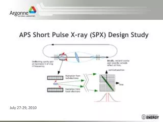
Short Pulse X-ray (SPX) at the Advanced Photon Source. A. Nassiri Advanced Photon Source. ICFA Beam Dynamics Mini-Workshop on Deflecting/Crabbing Cavity Applications in Accelerators The Cockcroft Institute, Daresbury, UK September 2010. Outline. APS Upgrade

E N D
Short Pulse X-ray (SPX) at the Advanced Photon Source A. Nassiri Advanced Photon Source ICFA Beam Dynamics Mini-Workshop on Deflecting/Crabbing Cavity Applications in Accelerators The Cockcroft Institute, Daresbury, UK September 2010
Outline • APS Upgrade • SPX scheme using deflecting cavities • Technical systems • R&D • Summary
APS Upgrade • The APS Upgrade (APS-U) project at Argonne National Laboratory (ANL) will provide high-energy, high-average-brilliance, short-pulse, penetrating hard x-rays in the range above 25 keVwith: • Nanoscale focal spots reaching < 5 nm above 25 keV; • Time resolution down to 1ps; • New or improved x-ray beamlines; • The technical capabilities required to fully exploit these upgraded technical components
SPX Scheme† y Scientific Goal: Generate short x-ray pulses using crab-cavity-based method. Technical Goal: Conduct R&D to demonstrate proof of concept which will lead to design and implement of a fully integrated SRF deflecting cavities system for the APS storage ring. X-ray pulse compression • A. Zholents, P. Heimann, M. Zolotorev, J. Byrd, NIM A 425, 385, (1999).
Technical Systems • Cavities • Cryomodule • Cryogenics • Low-level RF • High-power RF and waveguide distribution • Beam diagnostics • Timing and synchronization • Controls/Interlocks/ Machine Protection System
Cavities Single-Cell SC Cavity Input Coupler Baseline HOM Damper HOM Dampers LOM Damper Alternate Parameters for the Baseline Cavity Details in Haipeng Wang’s talk on Friday
2-cell Cavity Design Concepts Pi-mode cavity • 2-cell TM110 cavity operating in the pi-mode suffers from magnetic field enhancement on the iris. Results in little net defelcting voltage improvement. • 2-cell TM110 cavity operating in the 0-mode is difficult to damp SPM pi-mode due to limited coupling to dampers. • 2-1/2 cell Cavity • Center cell is used to couple the SPM into vertical damping waveguide. • 2 pi / 3 mode is not damped in the center cell and is utilized as the operating mode. • Difficult to manufacture and process center-cell geometry. Pi-mode 0-mode cavity Pi-mode 2-1/2 cell cavity SPM Modes
Alternate Cavity Design Baseline • Alternate Cavity Benefits • Larger stability margin for 200 mA beam current. • Single excited LOM plus two LOM waveguides produce less rf loading of dampers (assuming dual LOM waveguides are used) • More compact • Alternate Cavity Disadvantages • Additional waveguide penetration for second LOM waveguide, if needed. • Unproven design features • Magnetic field enhancement? Numerical results show adequate damping without enhancement • Multipacting enhancement? Experimental and numerical results do not show a problem • More complex helium vessel Alternate Details in Haipeng Wang’s talk on Friday
Cryomodule Main Parameters Preliminary Estimate of 2K Losses Estimated System Parameters Helium vessel cut-away • Helium vessel plates are integral with cavity end groups and utilize existing Nb material during construction. • Thermal properties of ‘uncooled’ outer portion of end groups must be analyzed. • Each helium vessel is fed individually by supply lines and a gas return pipe. Helium vessel with waveguides and blade-tuner rings
T2 T2 ID VC P P Deflecting Cavity Cryomodule Insertion 8000 mm ?? mm 190 mm 190 mm 2920 mm Space available for cryo-modules + bellows + … 107.3 mm V T1 B B B T1 V Gate valve Bellows Bellows 300 mm Thermal intercept 8 cavities 3500 mm Courtesy: L. Morrison
Schneider, Kneisel, Rode, “Gradient Optimization for SC CW Accelerators,” PAC2003 Refrigeration • Refrigeration @4.3K: • COPINV = 70 W/W • Carnot efficiency = 30% • Input power required = 230 W per watt at 4.3K • Refrigeration @2K: • COPINV = 150 W/W • Carnot efficiency = 18% • Input power required = 830 W per watt at 2K
ELBE CryoplantFZ-Rossendorf • Cryoplant hall: 17m x 10m • 220W @ 1.8K + 200W @ 80K, upgradeable to 380W with more comp & LN2 precooling • 417kW at full load (220W)
Cryoplant Costs • Requirements are calculated using • 312W for Q=1E9 • 200W for Q=3E9 • 161W for Q=1E10 • 152W for Q=2E10 • Same Qs, but ½ voltage • Equivalent load includes 300W for 5-8K intercepts and distribution sys. losses and 200W equivalent for 40-80K shield load. This extra load is a fixed value and assumed to be independent of the 2K load. • For cryoplants of this type, 1.8K operation adds 33% to plant size compared to 2.0K operation. *Fermilab is buying a new cryoplant for ILC string tests. Design capacity is 270W@2K + 300W@5-8K + 4500W@40-80K (= 1230W equivalent at 4.5K). Costs scale with the 0.7 power of plant capacity (per Byrns & Green, “An update on estimating the cost of cryogenic refrigeration,” 1998).
Beam loading Longitudinal voltage Vertical deflecting voltage Magnetic Field Electric Field Time
Beam loading RF Generator power No Tilt No Tilt
Beam loading RF Generator power Tilted Beam No Detuning Tilted Beam No Detuning
Beam loading • Beam Loading is offset and tilt dependent • Unless the operating parameter space is constrained… • required generator dynamic range is nearly infinite and >180deg control range is needed • wide range in optimal loaded Q (~ 1 decade for examples shown) • cavity-to-cavity electrical center alignment is important • Loaded Q not only influences power requirements, but also influences specification on Machine Protection System against uncontrolled beam offset • Need to consider longitudinal Robinson stability conditions for offset beam
Baseline HLRF System Design • 10kW klystron amplifiers, one per cavity • Common HVPS per sector • Master HVPS switching clock to correlate noise
Alternate HLRF System Design • 20kW klystron amplifiers, each driving two cavities • Magic-Tee hybrid used to split power • Common HVPS per sector
Diagnostics • Diagnostics to implement with source development: • RF BPM upgrade is crucial in maintaining / controlling electron beam trajectory during SPX operation. • RF phase detector measures bunch arrival time. • RF tilt monitor measures the chirp/tilt inside and outside of the SPX. • Optical diagnostics measures x-ray beam vertical profile, extracting information of electron phase, tilt angle and other information about the transverse deflection cavity operations. • Diagnostics to monitor residual effects • Sensitive rf tilt monitors and synchronized x-ray photon measurements outside of the SPX will be used to minimize the impact of SPX on other users around the ring. 22
Timing/Synchronization Requirements • Timing/Reference for Diagnostics • Within SPX Zone • Beam arrival time monitor • Six BPMs • Two RF beam tilt monitors • X-ray based tilt monitor • Outside SPX Zone • Two RF beam tilt monitors • X-ray based tilt monitor • Synchronous detection of residual effects • Master Oscillator • 351.9 MHz and 2815 MHz • Crab cavity LLRF • 2815 MHz phase reference • Calibration reference • Local oscillator • ADC clock • Phase reference for beamline lasers ( laser-pump/x-ray probe) Beamline lasers • High-peak power Ti-Sapphire • Pulse duration: 50 fs • Repetition rate: 1-270 kHz • High power, sub-cycle TH source • Pulse duration: <1 ps • Repetition rate: 1- 270 kHz • UV to mid-IR source • Pulse duration: <100 fs • Repetition rate: 1-270 kHz • High repetition-rate fiber laser system • Pulse duration: <200 fs • Repetition rate: 6.5 MHz
Specifications • Beamline timing ( Yuelin LI) • 100-200 fs stability ( fraction of x-ray pulse width) • S35 beamline timing ( Bingxin Yang) • Same as common mode ( ~7 picoseconds) • Cavity phase • <7 deg common mode • ~7 ps @2815 MHz • Keep intensity variation <1% • 0.03 deg uncorrelated ( ~30fs @2815MHz • Drift >100 Hz • Below 100 Hz corrected by orbit feedback system • Orbit motion <10% of beam size Problem • One meter of cable with • 7 ppm/degC • v/c=67% • Results in ~50 fs/deg C LBNL Femtosecond–Phase Stabilization System • Uses frequency offset in the optical domain • Optical frequency is offset by an RF frequency (110 MHz) • Offers a large leverage over stabilization in the RF domain • Six-order-of-magnitude • The frequency offset process is equivalent to a heterodyning process • Heterodyne (mix) original optical frequency with the offset optical frequency • Changes in the optical phase translate to identical changes in the 110 MHz beat signal • One degree of phase change in the 1530 nm optical domain translates to 1 degree of phase change in RF domain ~21 attoseconds LBNL Results • 2.2 km fiber • 19.4 fsrms @2850 MHz (60 hours) • 200 m fiber • 8.4 fsrms @2850 MHz (20 hours)
R&D Elements • Complete and test baseline and alternative cavities as a high priority (gradient, Q, Lorentz detuning, pressure sensitivity, HOM Q’s) • Develop tuner concepts for each option • Develop cryomodule concept for either option • Develop better options for mechanical alignment or cold adjustability • Develop low-impedance cold bellows • Evaluate HOM power above cut-off and where it goes • Determine cavity to cavity isolation spec for LLRF control • Evaluate multi-pole components for operating mode and coupling terms in transverse wakes from perturbations in symmetry • Quantify Operating mode leakage into LOM waveguide (fabrication tolerance) • Quantify effect of reflections from real loads & windows on achievable Q’s • Perform on-line test of realistic slice as early as possible to allow time for corrections (need to develop temporary cryo, controls & test plans) • Make normal conducting high Q cavity and develop LLRF system • Obtain Berkley system for 100fsec Synch • Link cavity and pump laser through ~100m fiber • Measure present laser jitter • Add beam phase lock loop to Main Storage Ring RF with Beam Arrival Time • Cavity Tilt Monitor
Summary • Continuing collaboration with JLab on baseline and alternative cavities design and cryomodule • Alternative cavity design provides more margin to instability threshold • Being investigated in parallel to baseline cavity • Encouraging initial results from prototype • Will down select in R&D phase • Design of damper and tuner will commence soon • Design modifications for improved cavity-to-cavity alignment or adjustments will be investigated • In the process of establishing a formal collaboration with LBNL on LLRF controller and timing/synchronization system • We believe, overall technical solution looks feasible but challenging in key parameters. • Phase stability • HOM damping • Alignment • Impact on the APS storage ring reliability • We have started a comprehensive R&D program to address these challenges in the next three years.