Download
1 / 63
1.16k likes | 1.76k Views
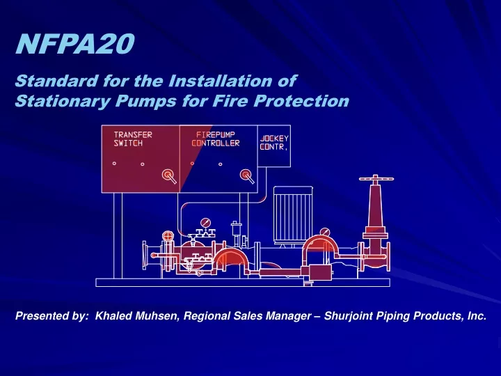
NFPA20 Standard for the Installation of Stationary Pumps for Fire Protection. Presented by: Khaled Muhsen, Regional Sales Manager – Shurjoint Piping Products, Inc. Purpose of a Fire Pump .

E N D
NFPA20 Standard for the Installation of Stationary Pumps for Fire Protection Presented by: Khaled Muhsen, Regional Sales Manager – Shurjoint Piping Products, Inc.
Purpose of a Fire Pump • To protect lives and properties against fire by supplying an adequate water supply to automatic sprinklers or standpipe systems • To meet building codes and insurance requirements
Codes and Standards • National Fire Protection Association - NFPA • Establishes the norms that governs all fire installation • Continuously revises the codes (Last issue 2003)
Listing Authorities • Underwriters Laboratories (UL) • Underwriters Laboratories of Canada (ULC) • Factory Mutual Research Corporation (FM)
Codes and Standards • NFPA Philosophy • A fire pump system should operate irrespective of any damage it may cause to itself • No element of the system under emergency conditions should: • Prevent a fire pump from turning on • Cause a fire pump to turn off • Changes to the code must be substantiated by data or experience (actual scenarios)
Codes and Standards • NFPA20 Structure: • Definitions (3 pages) • Centrifugal Fire Pumps (5 pages) • Positive Displacement Pumps (2 pages) • Electric Motors (1 page) • Diesel Engines (4 pages) • Controllers (12 pages) • Pump Installation and Related Components (10 pages) • Acceptance Tests and Maintenance (2 pages)
Water Supply • Where fire pumps are installed on a city main, a fire flow test should be performed to determine minimum and maximum supply pressures as well as suitability of supply for the fire protection system • Where adequate city supply water is unavailable, a suction tank or pit should be installed • Tank sizing must consider 150% of the fire pump rated flow • Total water requirements are defined in NFPA13 (Sprinkler Systems), NFPA14 (Standpipe Systems), NFPA15 (Spray or Mist Systems), Mains)
Pump Requirements “Centrifugal fire pumps shall be listed for fire protection service.” “Pumps shall furnish not less than 150% of rated capacity at not less than 65% of total rated head. The shutoff head shall not exceed 140% of rated head for any type pump.”
Pump Requirements Max Shutoff Head %Rated Head 140% 100% 65% %Rated Flow 100% 150%
Pump Sizing “A stationary pump for fire protection should be selected in the range of operation from 90 percent to 150 percent of its rated capacity. The performance of the pump when applied at capacities over 140 percent of rated capacity can be adversely affected by the suction conditions. Application of the pump at capacities less than 90 percent of the rated capacity is not recommended. The selection and application of the fire pump should not be confused with pump operating conditions. With proper suction conditions, the pump can operate at any point on its characteristic curve from shutoff to 150 percent of its rated capacity.”
Pump Sizing Pump Design Flow Head 100% Pump Rated Flow Flow 150% 90% 100%
Misinterpreted Code Requirement • Sizing the fire pump - a listed pump should be applied for flows from 90% to 150% of its rated point • Most fire pumps are sized to exceed the duty requirement of the fire protection system • The rated flow is a convention used to regulate the listing of pumps
Pump Requirements • FM & UL require that fire pumps have packing seals • ULC allows mechanical seals • Packing requires periodic adjustment and replacement as it hardens over time • The packing gland should be tightened until the seal leaks 30 drips per minute • If the gland is tightened to much, the seal receives no lubrication and will burn
Allowable Pump Types • Horizontal Split Case • Vertical In-Line • End Suction • Vertical Turbine
BENFITS Available in a wide flow and head range Serviceable without disturbing piping or driver Available in electric or diesel drive DRAWBACKS Large floor space requirement Restricts mechanical room layout due to direction of rotation More costly More difficult to service HSC Fire Pumps
BENEFITS Compact Serviceable Reliable Cost Effective DRAWBACKS Only available up to 1500GPM Electric Drive Only Requires suction strainer VIL Fire Pumps
BENFITS Moderate floor space requirement Flexibility in mechanical room layout Available in electric or diesel drive Serviceable DRAWBACKS Only available up to 1500gpm Single suction design limits hydraulic efficiency End Suction Fire Pumps
Used where a flooded suction cannot be maintained Underground water sources or below ground tanks with above ground pump room Vertical Turbine Fire Pumps
BENFITS Will operate under suction lift Available in electric or diesel drive Available over wide flow and head range DRAWBACKS More costly More difficult to service and install Vertical Turbine Fire Pumps
NFPA Required Pump Accessories Suction & Discharge Gauges Air Release Valve • Pressure Relief Valve • three pressure ranges • adjustable on site
NFPA Required Pump Accessories • Suction gauge must be of the compound type (capable of reading negative pressure or vacuum) • Discharge gauge must read two times the working pressure of the pump and not less than 200psi
Air Release Valve • 1/2” Air Release Valve is required • Exception: top centre-line discharge end suction and vertical fire pumps
Casing Relief Valve • 3/4” up to 2500usgpm • 1” over 3000usgpm • Should be set between the maximum suction pressure and minimum suction pressure plus the closed valve pressure of the pump • Piped before the fire pump discharge check valve
Isolation Valves • Suction OS&Y Gate Valve • Discharge Butterfly Valve • Both must be supervised • Discharge Butterfly Valve Installed after “Test Tee” and pressure sensing line
Hose Valve Systems • Provides testing means • Sized by pump rated capacity • There are hundreds of different thread types depending on jurisdiction - type should be specified on projects
Flow Meters • Does not replace a hose valve system • Flow meters must be listed for fire protection service • Gauge reading is a minimum of 175% the pump rated flow • Provides a testing means without wasting water • Flow meter is installed in bypass back to suction • Must be installed with isolation valves per manufacturer’s specifications • RULE OF THUMB:Annular Type - 10Ø upstream - 5Ø downstreamVenturi Type - 7Ø upstream - 5Ø downstream
Main Relief Valves and Waste Cones • Sized by pump rated capacity • Spring or pilot operated • Waste cone provides visibility of flow through the valve • When it is used: 1) Diesel driven systems 2) Electric systems ???
Main Relief Valve - Diesel Pumps psi Shutoff Head @ 10% Overspeed 179 Shutoff Head @ Rated Speed 165 130 30 20 GPM 1000 1500
Main Relief Valves and Waste Cones • Recommended on all diesel driven systems • Not required on diesel if maximum supply pressure plus 1.21 x closed valve pressure does not exceed system pressure rating • NFPA allows piping back to suction - NOT recommended • Relief valve should be set below maximum pressure rating of the system
Main Relief Valve - Electric Pumps Max Shutoff Head psi 180 130 Rated Head 60 20 GPM 1000 1500
Misinterpreted Code Requirement • Devices in the discharge piping - main relief or pressure reducing valves should only be installed where absolutely necessary • Valves introduce a failure mode and should only be used when required
NFPA Fitting Sizing Piping, Relief Valves, Metering Devices, and Hose Valves should be sized according to Table 2-20 on Page 20-13.
Pressure Maintenance Pump (Jockey) • Every system has a normal leakage rate that will result in a pressure drop • Jockey Pump will maintain the pressure in the system • This will prevent the main fire pump from starting for minor leaks
Jockey Pumps Jockey (pressure maintenance) pumps and jockey controllers need not be listed for fire protection service. “The primary or standby fire pump shall not be used as a pressure maintenance pump.” A jockey pump should be sized such that it CANNOT meet the flow demand of a single sprinkler fixture.
Jockey Pump Sizing • Jockey pumps should be sized for 1% of the flow of the main fire pump • Jockey pumps should be sized to provide 10psi more pressure than the main fire pump • Jockey pump should be sized so that it cannot meet the demand of the lowest flow fire protection fitting in the system
Fire Pump Operation • Fire pumps are designed to start on a pressure switch setting • Some fire pumps can be started automatically based on a deluge valve opening, or a remote signal • The pressure sensing line is the lifeline for the fire protection system
Fire Pump Operation • Pressure switches should be rated for maximum pressure conditions • Sensing lines must be 1/2” non-ferrous (copper) with two check valves with a 3/32” hole drilled in the flapper • Check valves are for damping of pressure when the pump starts to protect the pressure switch • Check valves are installed 5 feet apart and must open on a pressure drop in the sensing line • Check valves close when the pump starts • Jockey pump and fire pump sensing lines must be separate
110 100 95 90 50 Fire Pump Operation Stop Point Pump shutoff System gradually looses pressure psi boost Jockey start Fire Pump start Time period
Critical New Code Requirements (2003) • Extensive changes to NFPA20 including chapter numbers • Fire pump sizing will move from the Appendix to the main text of the code • Greater clarity on devices in the discharge piping • Provisions for the acceptance of electronic speed governors on diesel engines • Reference to NEMA ICS 14-2001 as Appendix B (Application Guide for Electric Fire Pump Controllers)