Download
1 / 26
260 likes | 442 Views
ICD Status. High Voltage Changes Invalid Alarms ICD channels in caladdress LED pulser & Taking Runs Calibration Data from Feb 5th Strange behavior of LED Calibration Data from Mar 5th How to proceed next?. ICD High Voltage Changes. High Voltage System conversion by Fritz Bartlett

E N D
ICD Status • High Voltage Changes • Invalid Alarms • ICD channels in caladdress • LED pulser & Taking Runs • Calibration Data from Feb 5th • Strange behavior of LED • Calibration Data from Mar 5th • How to proceed next? Alan L. Stone Louisiana Tech University
ICD High Voltage Changes • High Voltage System conversion by Fritz Bartlett • Global HV GUI will show green (holding) or turquoise (locked state) only when both voltage & current readbacks are within acceptable limits for data-taking • Minor alarm state (LO or HI) = yellow • Major alarm state (LOLO or HIHI) = pastel red • Saturated red color indicates a trip condition while pastel red indicates a major alarm in one or both readback values • Voltages cannot be changed while in locked state • HV cannot be raised above V_set value • ICD channels have very narrow Voltage limits • Voltages are very stable - PMTs very sensitive to HV change • Will need specific interface to deal with LO/HI & LOLO/HIHI alarms for ICD currents • Only I_trip exists at this time Alan L. Stone Louisiana Tech University
High Voltage Test Point Drifting • ICD HV - 128 pods in rack MCH116 provide voltage to 378 PMTs in detector • Not enough money or room for a new rack in MCH for one-to-one pod to PMT matching • Use 1:3 adjustable fanout boxes (1 input, 3 output V) • Set pod voltage in GUI in control room • 48 test points on front panel of fanout box • Safety bar – live voltages 800 V • Previously, we used a 1% resistor which was susceptable to moisture which left mineral deposits. This changed the resistance with time, so the test point voltages drifted! Did not affect the voltage received by PMT, but made the modification of voltages very difficult. • 48 set screws on each fanout box – 100 V variance • Match PMTs to minimize voltage difference between PMT sets • Ted Elzroth measured test points – no apparent drift after initial setup in December. Very good news! Alan L. Stone Louisiana Tech University
Sent email to Bill Lee to have the following alarms deleted ICD only uses three of the eight LV modules in the LVPS ICD_LVCP_PW09/12VB ICD_LVCP_PW09/8VC ICD_LVCP_PW09/8VD ICD_LVCP_PW09/8VE ICD_LVCP_PW09/6VH ICD LVPS does not have a magnetic field sensor (sits in rack PW09) ICD_LVCP_PW09/M* These two HV pods are not used (no cables connected - no PMTs in detector) CALS_HVC_SE11 CALS_HVC_SE11/STATE CALS_HVC_SE11/VOLT CALS_HVC_SE11/CURR CALS_HVC_SE12 CALS_HVC_SE12/STATE CALS_HVC_SE12/VOLT CALS_HVC_SE12/CURR These two pods show up as Offline or disabled in the channel HV GUI. Invalid Alarms Problem over weekend with ICD Preamp row in Supply GUI. What, why & how? Alan L. Stone Louisiana Tech University
Alan L. Stone Louisiana Tech University
ICD channels in caladdress • Backplanes of Southwest & Northeast crates have fiber order reversed “accidentally” • Affects only ieta = 12 & 14 • Used RU-106 source to test map • Instead of dismounting two 200+ kg crates to fix problem: • Change trigger summers on half of the L-type BLS cards (now L2) • Modify caladdress package for those channels specified as: • = -12 -14 for = 1-32,49-64 • = 12 14 for = 17-48 • Bob Kehoe modified caladdress last week – need to still verify Alan L. Stone Louisiana Tech University
Purpose of LED Runs • Long term monitoring of PMT response • The photomultiplier tubes for the Run II ICD sub-detector were recycled from the Run I ICD boxes • Each channel was individually tuned in order to achieve a mean MIP peak on the cosmic ray test stand • Only lever arm is the high voltage setting • Over a dozen PMTs have already been replaced • About a dozen channels have failed or dropped significantly in gain since the end of the Oct-Nov shutdown • Establish a real world baseline for the full ICD – from scintillator tile to the BLS card • Determine correction for channel to channel variation Alan L. Stone Louisiana Tech University
The Basics of the ICD LED Pulser • Scintillator LED Pulser (SLP) – borrowed from the Muon calibration system • ICD shares VME board with FPD – sits in MCH308 • Accepts external NIM test pulse trigger • VME controlled channel enable, trigger, amplitude and delay • Steve Doulas provided the documentation and expertise! • Excellent GUI created by Marc Hohlfeld! • DC offset resistively coupled to a TTL signal pulse • TTL pulse triggers a transistor which discharges a capacitor into a group of four LEDs • DC offset provides the bias voltage for these LEDs Alan L. Stone Louisiana Tech University
Taking ICD LED Runs • Detailed instructions now part of the Cal Shifters’ Guide (still being fine-tuned) • Needs to be given priority during periods without beam • A baseline still needs to be determined • What is the optimum delay time (between 0 and 170 ns)? • What DC offset(s) should be used? • The turn-on voltage as seen on the oscilloscope directly from the electronics is about 6.6 Volts. • The LED pulser needs to be issued a command to turn off during the prepare-for-run-1.2 download • There is currently no alarm to check that the ICD LED pulser is off during global data-taking • Bill Lee & Ulla Blumenschein working on this Alan L. Stone Louisiana Tech University
More on LED Pulser Runs > setup d0online> cd /home/d0icd/vme> ./lmb_int.py & • Voltage is adjustable up to 10.0 Volts in increments of 0.2 Volts • Delay is adjustable from 0 to 170 ns in increments of 2 ns • All Download is preferable – Read feature sets ALL to zero • The only way to turn off the pulser is to set ALL (voltage & delay) to zero - then click on Read - all fields should be 0.0 or 0! Alan L. Stone Louisiana Tech University
Last time... • Stephanie Beauceron took the full set of runs (six DC offsets at six different time delays) on Feb 6th! • Too much work – need to reduce the number of steps • hbook saved files very useful to make plots/printouts offline • From the spreadsheet, I was able to make plots for each channel (ADC counts vs DC offset and delay time) • Choose a delay time so the signal is sampled at or near the peak Ted Elzroth determined ADC count value for one good channel from each Cal Crate in which the ICD is part of the readout - [Crates 0,1,4,5,6,7,10,11]. Did this for each DC offset & time delay setting – 8 6 6 = 288! Alan L. Stone Louisiana Tech University
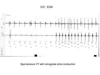
ICD-CAL Preamp/BLS Signal Shape Alan L. Stone Louisiana Tech University
ICD Beam Signal Alan L. Stone Louisiana Tech University
All ICD channels in Cal Crates 10 & 11 readout Alan L. Stone Louisiana Tech University
ICD in Cal Crate 0 Alan L. Stone Louisiana Tech University
ICD in Cal Crate 11 Alan L. Stone Louisiana Tech University
LED Pulser Runs • There is a difference in the timing between East/West • 180 feet SLP cable on East & 210 feet on West • SLP maximum delay is 170 ns • All channels are coming in very early • West appears to be near maximum, but East is even earlier • Dean added 130 ns delay to the trigger (both preamp and LED pulser) • This shifts the scale adding another 140 ns of delay range • Dropped two of the six DC offsets from the LED pulser runs Alan L. Stone Louisiana Tech University
Something Strange Happened... • Florian Beaudette took ICD LED pulser runs on owl shift of February 22 • 4 DC offsets (7.8, 8.2, 8.6, 9.0) & 6 Delays (0,10,20,30,40,50) • Wrote script renamehbkwhich changes cal_elec default hbook name to include DC offset & delay time • Next owl shift, Florian noticed that most of the ICD cells had about -1 GeV. • He looked in the crate_all_bad.txt file, noticing most of the cells reported were ICD • Both Florian, and the next shifter, Lee Sawyer, checked: • Pulsers (preamp & LED) were off & LV/HV was OK • redownloaded cal_prepare_for_run-1.2 Alan L. Stone Louisiana Tech University
More strange behavior • I looked at the hbook files on Feb 24th • only 2 of the 24 runs had signal - the rest showed only pedestal for all channels • The 2 with signal were at the same DC offset at 40 & 50 ns delay • Despite the LED pulser GUI reading all zeroes, it seemed the SLP card was still sending signals! • Ran cal_elec: all ICD channels were firing as one would expect if the LED pulser was on • I disconnected two of the four SLP cables - half of the ICD signals returned to pedestal (as seen in cal_elec) • The only immediate solution (we were in shot set-up) • I disconnected all SLP output cables from the SLP card in M308 • Mingcheng & Bernard took new pedestals - ICD channels looked normal again (eve of Feb 24th) Alan L. Stone Louisiana Tech University
Fixing ICD LED Pulser • I cannot explain it! • Eve of Feb 27th, I reconnected the SLP output cables • Dean & I looked at the VME page and LED GUI • Nothing unusual - I described my tests in detail in the logbook • I took several separate cal_elec runs, using different DC offsets & delay times - the SLP did not “lock-up” • What have we learned: • Shifters hesitate TOO LONG to page expert (generalization) • During physics data taking – Always fix problem ASAP! • Emails and Logbook entries are not enough! • Need for a NEW dedicated person to become ICD expert • I will help as much as I can… Alan L. Stone Louisiana Tech University
Calibration Data from March 5th • Ulla took fourteen runs: fixed DC offset of 8.6 V • delay time from 0-130 ns in increments of 10 ns • L3/DAQ work prevented her from going to 170 ns • Took about two hours • Primarily interested in optimizing delay time • What was the effect of Dean shifting trigger by 130 ns? • To verify the SLP did not “lock” in one state • Ulla ran a new cal_elec_ICD & looked at a few channels to watch for small changes from run to run • I took this step out after Stephanie tried the procedure, to make it easier - if this had been left in, I think Florian would have noticed a problem, so I will keep it from now on • Ted looked at the hbook files & created a spreadsheet Alan L. Stone Louisiana Tech University
Alan L. Stone Louisiana Tech University
Alan L. Stone Louisiana Tech University
Alan L. Stone Louisiana Tech University
Alan L. Stone Louisiana Tech University
What Steps should we take next? • Less than 2% difference between min/max ADC count value for West channels between 10 & 130 ns delay • East is still early - increase of 6-8% in ADC count value from 10 ns to 130 ns delay • Add cable to East? Or take separate runs for East & West? • Continue to remove the “black-box” treatment of ICD • Suggestions? Documentation is up-to-date. • 44 New PMTs arrived – a gift from Heidi and Dean - will ship to UTA for testing by Kaushik et al. (?) • Have commitment for tested PMTs at D0 by May 1st • Tentative plans: 2 week access in late May/early June & 4-5 week shutdown beginning in August • detector will open both times, so bad/marginal PMTs can be replaced Alan L. Stone Louisiana Tech University