Download
1 / 36
380 likes | 569 Views
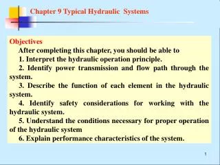
Chapter 9 Typical Hydraulic Systems and Some examples. Objectives After completing this chapter, you should be able to 1. Interpret the hydraulic operation principle. 2. Identify power transmission and flow path through the system.

E N D
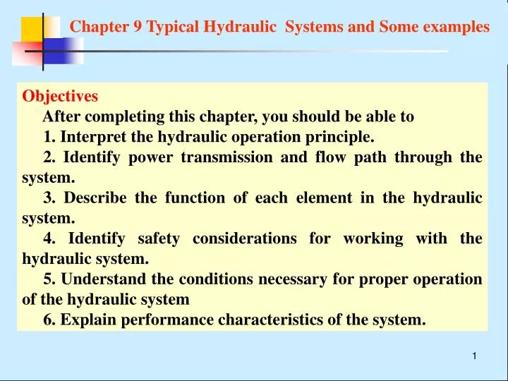
Chapter 9 Typical Hydraulic Systems and Some examples Objectives After completing this chapter, you should be able to 1. Interpret the hydraulic operation principle. 2. Identify powertransmission and flow path through the system. 3. Describe the function of each element in the hydraulic system. 4. Identify safety considerations for working with the hydraulic system. 5. Understand the conditions necessary for proper operation of the hydraulic system 6. Explain performance characteristics of the system.
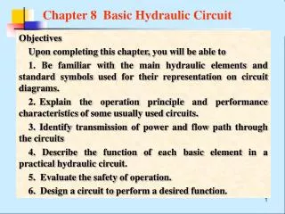
Chapter 9 Typical Hydraulic Systems and Some examples How to read a hydraulic system diagram ? (1)Identify the function and operation of an objective oriented machine and the machine’s requirements to its hydraulic system. (2)Browse the overall system, recognize hydraulic symbols and separate the system into several subsystems . (3)Analyze each subsystem, clarify which circuits constitute the subsystem, and comprehend the subsystem. (4)Analyze the interrelationship among subsystems. (5)Explain the operation of the system and the function of each control element. (6)Summarize the systematic characteristics.
9.1 Power Sliding Feed Unit System of Modular Machine Tool 1 Introduction YT4543 power sliding feed unit is a general component of modular machine tool which is used to accomplish feed motion. Mounted different spindle boxes the platform can carry out many machining jobs such as drilling, reaming, boring, milling, scraping end surface, chamfering, tapping and so on.
9.1 Power Sliding Feed Unit System of Modular Machine Tool The common work cycle is that first the cylinder has a rapid advance motion, second moves with the feeding motion at a slow rate, third moves further with another feeding motion at a slower rate, next stays for a predetermined time at the end of the stroke, after that returns rapidly, finally stops at the original position.
9.1 Power Sliding Feed Unit System of Modular Machine Tool Requirements for its hydraulic system The feed speed ranges from 6.6 to 600 mm/min , the maximum feed force is 45×103N. Additionally, the feed speed should be stable, the re-direction operation smooth, the power utilization reasonable, the systematic efficiency as high as possible and the heat amount generated as low as possible.
9.1 Power Sliding Feed Unit System of Modular Machine Tool 2 Identify elements 0. tank 1.filter 2.pressure compensated variable pump 3,7,9.check valve 4. pressure relief valve 5.back pressure valve 6.sequence valve 8,12.pressure compensated flow control valve 10.mechanically operated sequence valve 12.solenoid operated directional valve 13.pressure switch 14.cylinder 15.solenoid-controlled, pilot-operated, directional control valve
9.1 Power Sliding Feed Unit System of Modular Machine Tool
9.1 Power Sliding Feed Unit System of Modular Machine Tool The main directional control valve is a 5-way 3-position pressure operated spring centered valve which is actuated by a solenoid operated valve. To make the cylinder move in two different speeds during feed movement besides rapid approach and rapid return stroke, two pressure regulating valves are arranged in series.
9.1 Power Sliding Feed Unit System of Modular Machine Tool A mechanically operated 2-way 2-position direction control vale is used for the redirection from rapid motion to first feed. A two-way two-position solenoid operated direction control valve is used for the redirection from first feed motion to second. A dead iron block is used to limit the position of the platform as to ensure dimensional accuracy of the feed motion.
9.1 Power Sliding Feed Unit System of Modular Machine Tool 2 Schematics (1)Rapid movement When the start button is pressed, it energizes the solenoid 1YA, causing the 4/3 solenoid operated directional control valve to its left position. As a result, the main directional control valve shifts to its left position.
9.1 Power Sliding Feed Unit System of Modular Machine Tool Now flow path is The supply line: 0→1→2→3→main valve(its left position) →10(its down position) →13(its blank end) The return line: 13(its rod end)→main valve(its left position) →10 (its down position) →13 (its blank end ) A differential circuit is used for rapid advance
9.1 Power Sliding Feed Unit System of Modular Machine Tool Please note: The cylinder moves at a rather high speed. The cylinder is connected in a differential circuit, on the other hand, the pressure compensated variable displacement pump delivers the highest flow rate to the cylinder.
9.1 Power Sliding Feed Unit System of Modular Machine Tool (2)First feed movement As soon as the cylinder actuates valve 10, it closes stopping flow through it and allowing fluid to move to the cylinder only through valve 8, thus reducing its speed. Because of both load and throttle action, the systematic pressure rises, valve 6 opening and valve 7 closing. The fluid from the rod end of the cylinder returns to the reservoir through valve 6 and back pressure valve 5.
9.1 Power Sliding Feed Unit System of Modular Machine Tool Now flow path is as following: The supply line: 0→1→2→3→main directional valve (its left position)→8 →11(its right position) →13(its the blank end ) The return line: 13(its rod end )→main directional valve (its left position)→6→ 5→0.
9.1 Power Sliding Feed Unit System of Modular Machine Tool Please note: Because of both load action and throttle action, the pump reduces delivery flow rate so as to meet the needs of feed motion. The feed speed can be adjusted by pressure compensated flow control valve 8.
9.1 Power Sliding Feed Unit System of Modular Machine Tool (3)Second feed movement As soon as the cylinder comes in contact with the limit switch L2 which energizes the solenoid 3YA, valve 11 closes stopping oil through it and allowing oil to move to the cylinder only through valve 12, thus further reducing cylinder speed because the flow area of valve 12 is smaller than that of valve 8.
9.1 Power Sliding Feed Unit System of Modular Machine Tool Now flow path is as follows: The supply line: 0→1→ 2→3→ main directional valve (its left position)→ 8→12→13(it blank end) The return line: 13(its rod end)→ main directional valve (its left position) →6→5→0.
9.1 Power Sliding Feed Unit System of Modular Machine Tool Please note: The cylinder extends with a slower rate because the flow area of the pressure compensated flow control valve 12 is smaller than that of the valve 8. The second feed speed can be adjusted by valve 12.
9.1 Power Sliding Feed Unit System of Modular Machine Tool (4) Halts at the dead iron At the end of the stroke the platform is blocked by a dead iron block and halts here, thus the system pressure further rises. When the system pressure reaches the preset level of the pressure switch, the pressure switch sends an electric signal to the timer. After receiving the signal the timer starts timing. The setting of the timer can be adjusted within definite range.
9.1 Power Sliding Feed Unit System of Modular Machine Tool (5) Return rapidly Having reaching the setting the timer sends a signal which energizes 2YA, simultaneously de-energizes 1YA and 3YA. Thus the 4/3 directional control vale is shifted to its right position, then the main valve is shift to its right position. The oil from the pump flows to the rod end of the cylinder and the oil pushed by the piston returns to the reservoir.
9.1 Power Sliding Feed Unit System of Modular Machine Tool Please note: The pump delivers highest flow rate to the cylinder and the annular area of cylinder is substantially small. Therefore, the cylinder returns rapidly to original position.
Tab. 9—1 The action sequence of solenoids and mechanically operated directional control valve 9.1 Power Sliding Feed Unit System of Modular Machine Tool (6) Stop at the original position After the platform returning to the original position the limit switch sends a signal. All direction control valves are de-actuated and the pump is unloaded. The action sequence of solenoids and the mechanically operated directional control valve is tabulated in Tab. 9--1
9.1 Power Sliding Feed Unit System of Modular Machine Tool The system has several unique operational features: (1) Use of the solenoid valve,pilot operated directional control valve, pressure switch, timer, limit switch and dead iron block ensures the automatic accomplishment of the work cycle. (2) The speed at rapid advance is much higher than the feed speed. A differential circuit and a pressure compensated variable displacement pump meets the needs of rapid advance. (3) The return speed is much higher than the feed speed too. The smaller annular piston area and the pressure compensated variable displacement pump meets the needs of the rapid return. (4) The solenoid-controlled, pilot-operated, directional control valve with bi-directional dampers can ensure the redirection smoothness.
9.1 Power Sliding Feed Unit System of Modular Machine Tool (5) A mechanically operated directional vale, a 5/3 directional control vave and a sequence valve as the redirection from rapid advance to first feed not only ensures the position accuracy but also higher reliability and smoothness. (6)Use of a solenoid directional control valve as the redirection from first feed to second can meet the systematic needs since the two feed speeds are low. (7) Flow regulating valves in the meter-in circuit not only ensures to adjust the feed speed conveniently but also ensures the stability of the feed speed (characteristic of the valve itself).
9.1 Power Sliding Feed Unit System of Modular Machine Tool (8) The back pressure valve not only ensures that the cylinder may endure a certain overrunning load but also prevents air from entering to the system. That is, the back pressure valve may ensure the stability of the feed speed. (9) Use of the pressure compensated variable displacement pump as well as the direction control neutral position unloading ensures the system to utilize power reasonably and to run efficiently, accordingly to generate less amount of heat.
9.3 Hydraulic system of 8 ton hydraulic truck crane A truck crane is a kind of general mobile hoisting machinery which is a crane mounted on a truck chassis. An 8 ton hydraulic crane primarily consists of a hoisting mechanism, a slewing mechanism, aderricking or luffing mechanism, aboom telescoping mechanismas well as anoutrigger operating mechanism. The operations of all these mechanisms are accomplished hydraulically except travel propelling.
9.3 The hydraulic system of 8 ton hydraulic truck cranes The system requirements of a truck crane are as followings: (1) Outriggers should be locked reliably whether during a work cycle or during traveling. (2) The hoisting mechanism should work within a wide speed range and with a finer speed control feature. On the other hand, the hoisting mechanism circuit should function to limit the lowering speed so as not to drop by the action of a load。 (3) The derricking mechanism and telescoping mechanism should function to be locked and to limit the lowering speed. (4) The work safety and operating reliability are very important.
21 8 25 9 15 18 7 7 23 20 24 6 14 17 A 5 4 13 16 19 22 10 3 B Fig. 9-4 hydraulic system diagram of an 8-ton truck crane 12 2 1 1. pump 2.filter 3. 3-way, 2-position manually operated directional control valve 4,12.pressure relief valve 10.front outrigger cylinder 5,6,13,16,17,18. 4-way 3-position directional valve 7,11.dual pilot operated check valve 9. locking cylinder 8.aft outrigger cylinder 14,17,19. counterbalance valve 20.brake cylinder 21.flow control valve 9.3 The hydraulic system of 8 ton hydraulic truck cranes
21 8 25 9 15 18 7 7 23 20 24 6 14 17 A 5 4 13 16 19 22 10 3 B 12 2 1 9.3 The hydraulic system of 8 ton hydraulic truck cranes A gear pump(pmax=21MPa,V=40mL/r,n=1500r/min) is attached to the engine through the gear box. The pump draws hydraulic oil form the reservoir through a centrally mounted rotating junction, then high-pressure oil is directed to actuators by directional control valve group A and B. Valve 12 is used to prevent the hydraulic system from overloading. The preset level of the valve is 19MPa. an actual pressure can be read via a pressure gage. The system is an open-center system.
9.3 The hydraulic system of 8 ton hydraulic truck cranes Outriggers are used to stabilize the truck during lifting operations. All tyres must be suspended. outriggers should be retracted during the truck traveling. (1) The outrigger operating subsystem Two front outrigger cylinders are controlled by valve 6, while two aft outrigger cylinders are controlled by valve 5. The two directional valves arranged in series. A double pilot operated check valve is arranged on each outrigger cylinder to ensure the outrigger cylinder to be locked reliably to prevent the outrigger cylinders from retracting during lifting operations and from extending during traveling due to leakage.
9.3 The hydraulic system of 8 ton hydraulic truck cranes A weight should not only be raised/lowered within a wider speed range but also be suspended in the air. A ZMD40 axle piston motor is used to drive the winch. The speed-adjusting and redirecting are accomplished by varying the flow area of valve 22. A counterbalance valve is used to limit lowering speed to prevent a weight from overrunning. The brake is used to mechanically lock the hoisting motor. A flow control valve is used to ensure to take off brake slowly and to put on brake quickly. (2) Hoisting subsystem
9.3 The hydraulic system of 8 ton hydraulic truck cranes When the brake taken off, high-pressure oil first enters the motor and makes the motor create torque then take off the brake, which prevents a weight from dropping. When the hoisting motor put on brake the hydraulic oil in the brake cylinder returns immediately to the reservoir, which ensures the hoisting motor is braked quickly.
9.3 The hydraulic system of 8 ton hydraulic truck cranes (3) Main boom telescoping subsystem The telescoping section is driven by a long single-class cylinder. The telescoping section extends to a desired length before lifting duties and retracts before traveling. A special counterbalance valve is arranged in the return line to ensure the telescoping section to be locked to a desired position, and to prevent the telescoping section from retracting at an overrunning speed, that is, to ensure the telescoping mechanism to work safely.
9.3 The hydraulic system of 8 ton hydraulic truck cranes (4) The derricking mechanism subsystem The derricking mechanism , via changing boom angle in a vertical plane, is used to change the working radius to suit the demands of various duties. The derricking mechanism should change boom angle steadily under a load. Like the telescoping device circuit, a special counterbalance valve is used to ensure the boom to be locked to a desired angle, and to prevent the boom from lowering at an overrunning speed.
9.3 The hydraulic system of 8 ton hydraulic truck cranes (5) The slewing mechanism subsystem A slewing mechanism make a crane enable to perform hoisting duties in any direction. The slewing mechanism of an 8-ton hydraulic truck crane is driven by a ZMD40 hydraulic motor. The rotational speed of the crane superstructure is 1-3r/min. No buffer elements are arranged in the system since the crane is a small-size crane and the rotating inertia is not very large.
9.3 The hydraulic system of 8 ton hydraulic truck cranes To summarize, the system have the following features: (1) When either a weight lowering, or the telescoping section retracting or the derricking mechanism increasing working radius, the mechanisms are all exerted the overrunning loads, therefore, special counterbalance valves must be arrange in the return lines of these mechanisms. (2) As working situations vary substantially and all mechanisms are operated frequently, in general, the spring-return directional valves are used to control various actuators. When each directional valve is located in its neutral position all actuators stop moving and the pump is unloaded.