Download
1 / 24
260 likes | 409 Views
Basic concept The NSW chambers are assemblies of Micromegas monolayers, TGC’s and spacer/stiffeners. In order to simplify the assembly procedures we propose to construct the monolayers such that: they are sufficiently strong, rigid, stiff, and gas tight that they can be manipulated,

E N D
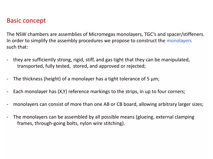
Basic concept • The NSW chambers are assemblies of Micromegas monolayers, TGC’s and spacer/stiffeners. • In order to simplify the assembly procedures we propose to construct the monolayers • such that: • they are sufficiently strong, rigid, stiff, and gas tight that they can be manipulated, • transported, fully tested, stored, and approved or rejected; • The thickness (height) of a monolayer has a tight tolerance of 5 μm; • Each monolayer has (X,Y) reference markings to the strips, in up to four corners; • monolayers can consist of more than one AB or CB board, allowing arbitrary larger sizes; • The monolayers can be assembled by all possible means (glueing, external clamping • frames, through-going bolts, nylon wire stitching).
Essential construction element: the monolayer • Monolayer material minimalisation: only AB, CB, drift spacers and seal strips at edges • Monolayer is glued together and is NOT repairable; • does not deform under gas pressure; • has a precise height (thickness): var < 5 μm; • allows the thinnest possible (low cost, good thickness precision) pcb’s(R&D); • drift spacers in gas (drift) volume: ~100 pcs per m2(R&D)) such that: • small dead surface for track detection; • drift spacer induced discharges: should not occur (R&D).
Monolayer assembly step 1 Spacers on Cathode Boards (CBs) Any table • non-precision spacer: • height: 4.70 mm (mold injection)for 5mm drift gap • dia. 5 mm • optional: hollow cylinder: wall thickness 0.8 mm: allows assembly by layer stitching • Spacer pitch: square pattern, pitch 100 – 200 mm (R&D) • Cathode Boards (CB): single sided (segmented) Cu • Thickness tolerances: subject of (R&D) • Tool (template) for rapid positioning of spacers • Apply UV curing glue (check ageing effects(R&D))
DriftSpacer Application Tool • Use UV curing glue, cured by UV LEDs (ageing tests R&D) • apply 100 spacers on CB in 30 minutes per m2 Ref Spring (cushion) O-ring CB UV-LED Any table
Resistive silk screen printing on Anode Board (AB) Photoresist Avalanche Gap Pillars + DriftSpacerPedestals AB + photoresist pillars any table
Mesh on Anode Board Mesh-in-frame any table
Preparation (in design) of the Anode Boards (ABs): Micromegas support (photo resist) Pedestal for spacer dia. 5 mm Micromegas AB (0.8 – 1.0 mm)
Construction of monolayers Bridge: assembly of straight edges + CB board suckers CB + spacers + edge gas seals AB + pillars + pedestals Granite flat table
Construction of monolayers Gauge blocks: define thickness monolayer (σ < 5 μm) Gas seals at edges: undersized, glue sealed Granite flat table
Mesh fixation in plane Plane Edge Seal Edge dyke DriftSpacerPedestal DriftSpacer CB board Epoxy Glue Epoxy Glue AB board
The effect of thickness variations in the AB and CB pcb’s Muon COG of primary ionisation charge We measure the COG of the primary charge of the muon track in the gas-filled drift volume. This point is displaced in Z and read-out by the strips. As a consequence, the COG (Z) of the drift volume causes an error dZ . sin (α) in ‘R’. Since the distance between the outside planes of the AB and CB boards is precise, the thickness variation of both boards comes in: equal variation (i.e. both too thick by the same amount) cancels the error in the gas layer COG. α AB CB dZ
Strategy for tolerance on Z (COG) of drift volume • a solid MonteCarlo simulation including diffusion (significant at large drift distance) • with dR/dZ as a function of the radial distance as result; • a systematical study of the thickness variations of commercial pcb’s in terms • of thickness, batch, position on board (edges, corners) • Selection of boards: combining selected AB and CB boards for chamber sections • at large radial distance.
Two tools are required for the production of monolayers: Tool 1: granite table with thick vacuum sucker sections to permit doubling pieces; Tool 2: bridgeto keep top plane of (assembly of) CB boards in plane within 5 μm.
Tool 1: granite table with sucking fixators Large monolayers (combination of 2 or more ABs): AB CB doubling piece • Glue strip ends together with (permanent) aux. joint plate (doubling piece) • interconnect (wire bond) strips • The pattern of the sucking pad’s leaves space for the doubling pieces • The sucking pads have a precise height (thickness) ~ 3 μm (mesh + Si rubber) sucking pad Granite flat table
Tool 2: bridgeto keep top plane of CB boards in plane within 5 μm The Bridge is an assembly of straight edges with spacing equal to the pitch of the drift spacers (~ 100 mm). Carbon fiber frame
Granite flat table Sucking pads Fix sucking pads (= Y ref) at bottom of straight edge by means of flat table. Elimination of non-flatness of granite table!
lifting mount Granite flat table straight edges Pitch equals drift spacer pitch
Construction of bi-layers (doublets) • Assembly of: • two monolayers • spacer: • could be (interconnected) bi-spacers (same X,Y position as in monolayer) • could be (machined) honeycomb • could be polyester wire (1.000 mm dia). • Height verification after assembly CB AB AB CB Granite flat table
(X,Y) alignment of Anode Boards (AB’s): Idea of Saclay: Rasnik code in Cu at upper and lower edges
Assembly of: • two duallayers • quad spacer: • could be interconnected spacers • could be (machined) honeycomb • could be plastic wire Construction of quadlayers Granite flat table Height verification after assembly
Construction of chamber stations • Assembly of: • two quadlayers • spacer: • made from G10 plates, bars, profiles • has 3 or more external temporally references: only precise in length (height). • includes RasnikInPlane system (2 cams, 4 diff. plates, 4 light sources) • readout during construction (calibration: ‘straight’ values). Spacer (stiffback, cross plate, longbeam, InPlaneRasnik systems) Quad layer Granite flat table
USB Pixel CMOS chip (taken out 10 $ webcam) Diffraction Plate lasers (out of pointer!) Readout USB webcam: any processor
Construction of chamber stations: fixing the 2nd quad layer Spacer (stiffback, cross plate, longbeam, InPlaneRasnik systems) Quad layer Quad layer Granite flat table
Alignment of Micromegas PCB (AB): • - Integrate Rasnik mask in Cuof all ABs: • Record (X,Y) positions in each corner (4x) by means of 4 cam’s • adjust (X,Y) position of each corner by means of (X,Y) actuator at each corner, • at each monolayer • Also Z values can be measured (quality control)! Cam Actuator Granite flat table