Download
1 / 36
360 likes | 507 Views
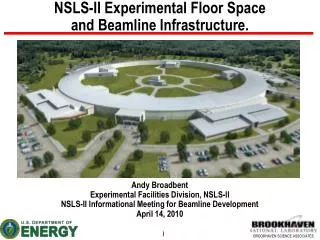
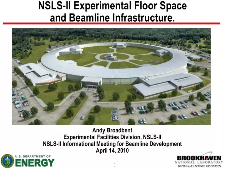
NSLS-II Experimental Floor Space and Beamline Infrastructure. . Andy Broadbent Experimental Facilities Division, NSLS-II NSLS-II Informational Meeting for Beamline Development April 14, 2010. Summary. Experimental Floor Space and Standard Beamline Territory Standard Radiation Enclosures

E N D
NSLS-II Experimental Floor Space and Beamline Infrastructure. Andy BroadbentExperimental Facilities Division, NSLS-II NSLS-II Informational Meeting for Beamline DevelopmentApril 14, 2010
Summary • Experimental Floor Space and Standard Beamline Territory • Standard Radiation Enclosures • Front Ends • Standard Utilities Pack for Beamlines • Laboratory and Office Buildings (LOBs).
NSLS-II Site Plan LOB 1 LOB 2 LOB 5 Main Entrance Laboratory Office Buildings Five in fully built-out configuration Booster Ring Main loading dock and road access to center of ring Service Building- one per pentant N LOB 3 LOB 4
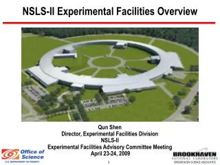
NSLS-II Facility Overview Layout Spaces for nine long Insertion Device Beamlines. One is allocated for the project nanoprobe beamline (in red). Lengths >250m possible. N
Beamlines passing outside the facility require a low level “bypass”, this gives the opportunity for extra floor space …. gives about 6m of extra beamline length on experiment floor. Extra 10’ of floor length 6’9” typ Normal vibration isolation joint position Alternative vibration isolation joint position
Standard and Extended Length Floor Areas • Additional 10’ radial floor distance (gives additional 6m on beamline length) where by-pass corridors are located. • Approximately 30% of periphery of facility • The LOBs are also designed to act as a corridor for the experimental floor giving another area of extended length beamlines. • Approximately 50% of periphery of facility. • The standard length floor at 16 beamline positions. • The extended length floor is available to 44 beamlines.
NSLS-II Experimental Floor Layout (Extended) Refer to Drawing LT-XF-CF-1008 for full dimensions of all beamlines.
NSLS-II Experimental Floor Layout Very standard floor access aisles Need access to ID FEs only (30 doors) Tunnel floor is 200mm higher than experimental floor (beam height at 1200mm, and 1400mm on experimental floor). Sector floor layout designed to optimized space. Safety emergency egress requirements Strong preference to include a duck-under route wherever possible to meet the 75’ “common path of travel” in BCNYS regulations. Some alternatives if a duck under is not compatible with the scientific requirements
NSLS-II IXS Beamline Hutch Layout High beta straight area with extended floor. Note that building over the egress aisle is justified only by scientific requirements and requires express written approval. The aisle will be relocated taking a portion of the BM/TPW sector. Ratchet wall First Optics Enclosure (FOE) End Station 1 Duck under route(relocated) End Station 2 Egress aisle(relocated with permission)
Two Possible IR Beamline Layouts Storage Ring Tunnel BM-B Dipole Magnet BM-A Dipole Magnet IR beamline passes over useable BM beamline IR beamline passes under BM FE, through ratchet wall to unusable ID floor area*. Experimental Floor * There are three unusable ID ports, (2 x RF and 1 x injection)
NSLS-II Project Beamline Location Constraints and Preferences.
Hutch Shielding Thicknesses * Shielding given is for sidewalls/roof/downstream wall, in mm. See also document “Guidelines for NSLS-II Beamlines and Front End Radiation Shielding Design” by Job and Casey, May 2008 for explanation and assumption. http://groups.nsls2.bnl.gov/eshqa/Lists/Announcements/Attachments/13/shielding%20guidelines%20for%20beamlines.pdf
Typical Front End Configuration Relatively Minor Variants for Canted Configuration and Damping Wiggler Beamlines.
Front End Interface Point Interface point; 6” Conflat on isolating gate valve, centerline 1400 mm from experimental floor, 155mm downstream of nominal shield wall position. A note on vacuum isolation; Differential pumps, with fast sensors can be used with approval from the vacuum safety committee. Beamline isolation windows are not mandatory.
Beamline Standard Utilities Pack • Requirements, Specifications and Interfaces document defines: • The beamline interfaces to conventional facilities and accelerator systems; • The beamline utilities at the point of usage. • Extensively reviewed and approved. • Reference document for design of beamlines; • Key specifications available in the Beamline Design Guide*. * copies will be available on request within ~two months, the information within is NOT required for the proposal.
Standard Utility Provisions - Electrical • Each beamline has 2 x 30 kVA transformers for “sensitive” and “non-sensitive” power. • Expected total electrical load <30kVA / beamline- at 50% transformer loading the hum noise will be negligible. • Aim to dissipate 60% of electrical power into the chilled water system – helps maintain high temperature stability in experimental hall. Use water cooled racks, as used for accelerator PSUs. • Small distributed UPS system to be included in beamline racks as required.
Standard Utility Provisions - Water • High quality de-ionized Low conductivity Water (LCW) for cooling of accelerator components, front ends and beamline optics. • 12 GPM average, 15 GPM peak allowed per beamline. • Pressure is 100 psi nominal, 150 psi max. • 85F +/- 0.2 F (29.5+/-0.1C). • Piping comes through ratchet wall from SR tunnel into FOE. • Chilled water for cooling of electronics racks and some end station equipment (eg furnaces, pumps, etc). • 3 GPM average, 6 GPM peak allowed per beamline. • Pressure is 100-120 psi nominal, 150 psi max. • 53F inlet temperature (20F temperature rise assumed at full rated flow and power removal). • Piping comes from roof of RF tunnel along top of beamline.
Standard Utility Provisions - Other • Liquid nitrogen. • 40 Gal/hr average allowed per beamline (dominant usage from DCMs on DW beamlines). • Pressure is 30-45 psi nominal. • Piping around facility above the SR tunnel, with drops at each ID beamline. • Gaseous nitrogen. • 20 cfm maximum allowed per beamline (main usage; purge gas and IR spectrometers etc). • Pressure is 30 psi nominal, 125 psi max. • Piping runs adjacent to LN2 system. • Compressed air. • 10 cfm maximum (intermittent) allowed per beamline (main usage; valves, air skates etc). • Pressure is 75 psi nominal, 125 psi max. • Piping runs from SR tunnel through ratchet wall into FOE. • Exhaust • Exhaust system above walkway allows HEPA filtered extraction to be linked in at any beamline position.
Control Systems • Aim to standardize much of the hardware, eg motion controls – currently being evaluated by BL controls working group. • Wiring standards currently in development. • EPICS for lower level accelerator and beamline controls. • Expect to standardize on one or two User interface packages (work in progress).
Laboratory Office Buildings (LOBs) • Based on detailed analysis and benchmarking with other facilities, an expanded LOB was specified to satisfy the needs of the NSLS-II community • In general, 8 laboratories and 2 electronic work areas plus a machine shop will be available as shared facilities in each LOB to support user/staff activities at the neighboring beamlines : • 3 wet labs, 2 dry labs • 1 shared special purpose sample characterization lab • 1 mechanical assembly lab, 1 vacuum prep lab • 2 shared electronic work areas, 1 shared machine shop • Adequate temporary storage space will be available for receiving and staging • 75 office spaces will be available to support users & staff but 17 of these spaces accommodate 2, 4, or 6 people sharing them – Total occupancy 124
LOB First Floor Plan • 57 One person Offices • Two people Offices • Six people Offices • Wet Laboratories • Dry Laboratories • Machine Shop • Conference Rooms • 1 Loading/Storage Area 30 { { Total = 38,000 gsf Each Lab = 480 nsf
Cross Section Mechanical Penthouse Office Area Lab Area
Initial Dry Lab Equipment List Initial list produced for space estimation purposes only. LOB build package includes benches, sinks, cupboards , safety shower, etc. Removable / specialist lab equipment will be part of separate budget.
Initial Machine Shop Equipment List The five machine shops around NSLS-II will be expected to specialize to some extent – for example one of the five may have a larger milling machine.
Utilities and Services & ESH Considerations The LOB plans are available for viewing (heavy set of drawings)!