Download
1 / 12
130 likes | 847 Views
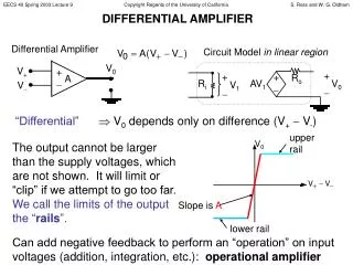
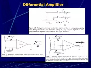
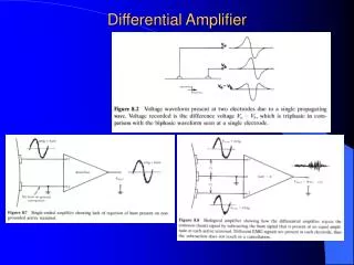
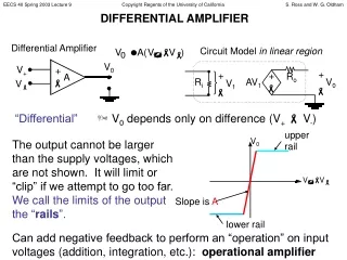
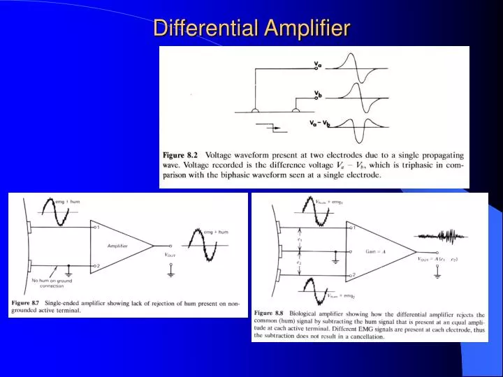
Differential Amplifier. EMG Signal Processing. EMG Amplifier Specifications. Amplifiers should be described by the following: If single, differential, double differential Input impedance Common Mode Rejection Ratio (CMRR) Signal to noise ratio Actual gain used Frequency range of amplifier.

E N D
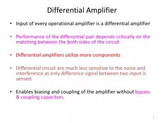
EMG Amplifier Specifications • Amplifiers should be described by the following: • If single, differential, double differential • Input impedance • Common Mode Rejection Ratio (CMRR) • Signal to noise ratio • Actual gain used • Frequency range of amplifier
Noraxon Telemyo EMG Amplifier • Input Noise < 1 μV RMS • Differential Input Impedance 16 Meg Ohms • Common Mode Rejection Ratio CMRR 85 dB • Frequency Response 16 – 500 Hz • Throughput Circuit Gain 1000
Reports on surface EMG should include: Electrode material (Ag/AgCl) Electrode geometry (disc, bars, rectangular) Size (diameter, radius, width x length) Use of gel or paste, alcohol applied to cleanse skin, skin abrasion, shaving of hair Interelectrode distance Electrode location, orientation over muscle with respect to tendons, motor points and fiber direction Intramuscular wire electrodes should be described by: Wire material (stainless steel) Single or multi strand Insulation material Method of insertion (hypodermic needle) Depth of insertion Single or bipolar wire Location of insertion in the muscle Interelectrode distance Type of ground electrode used, location Electrodes
EMG Amplitude Root Mean Square Average Rectified Value
EMG Linear Envelope • Full wave rectify the EMG • Low pass filter with a time constant?
EMG Filtering • Since the power density spectra of the EMG contains most of its power in the frequency range of 5-500 Hz at the extremes, surface EMG should not be filtered above 10 Hz as a low cutoff and below 350 Hz as a high cutoff. • Intramuscular signals should be filtered in the 10-450 Hz range.
The Median Frequency is defined as the frequency that divides the power spectrum in two regions having the same power or area under the Amplitude – Frequency Curve EMG Frequency Spectrum • Explain of Power Spectrum should include: • Time epoch used for each calculation • Type of window used prior to FFT (Hamming, Hanning) • Number of zero padding points • Equation used to calculate Median or Mean Frequency • Muscle length or fixed joint angle
EMG - Force • Recruitment of a motor unit. A quanta of force in contributed to the muscle contraction; however, the contribution to the EMG signal amplitude depends on the proximity of the detection surfaces of the electrode to the nearest fibers of the recruited motor unit. • A newly recruited MU will increase its firing rate as the force demand increases. • The force increase rapidly as a function of the increasing firing rate, whereas the contribution to the amplitude of the EMG signal increases less rapidly
EMG Normalization • Subjects should be adequately trained to elicit an MVC. • Provide subjects with immediate feedback of obtained force/torque. • Give the following information relative to normalization: • How the subjects were trained to obtain MVC • Joint angle or muscle length • Rate of force development • Velocity of shortening or lengthening • Change in muscle length • Range of joint angle in non – isometric contractions • Load applied in non – isometric contractions • When normalizing the amplitude of the EMG signal, do so at values less than 80% MVC. Above this level the EMG signal and the force (torque) are exceptional unstable and do not provide a suitable reference point (De Luca, JAB 13, p. 154)
EMG Crosstalk • Make every effort to determine that EMG crosstalk from muscles near the muscle of interest did not contaminate the recorded signal • Select an appropriate electrode size, interelectrode distance and location when working on an area where many narrow muscles are tightly gathered • Care also should be employed when recording surface EMG from areas with subcutaneous adipose tissue as it is known that adipose tissue enhances crosstalk.