Download
1 / 13
130 likes | 193 Views
Photovoltaic Cells. Paula Warren. What is a photovoltaic cell?.

E N D
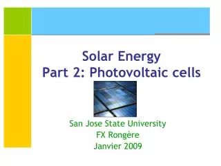
Photovoltaic Cells Paula Warren
What is a photovoltaic cell? It converts solar light into electricity and heat. Some materials exhibit a property known as the photoelectric effect that causes them to absorb photons of light and release electrons. When these free electrons are captured, an electric current results that can be used as electricity. PV cells made of a form of silicon. Could be single crystalline/mono-crystalline, polycrystalline, ribbon and sheet crystalline, or thin-layer crystalline silicon. Silicon is the most highly developed PV material and is the one most likely to succeed in large scale applications. If you can remove the heat from the PV modules, it is able to improve the electricity generation.
How it Works Semi-conductors are solids with electrical properties between metals and insulators. Conduction Band Valence Band e- valence band, results in a hole, (+) chg; e- move freely via motions of e- to fill vacancies e- conduction band, moves freely since all orbitals in the band are empty An e- in a conduction band and a hole in the valence band are called mobile carriers. Energy Band gap
Flow of Electrons • Need to produce a flow of e- so that after the sunlight hits the silicon, and e- are promoted to conduction band, they have a direction to go and do not fall back into the valence band. • If some of the semi-conductor’s atom are replaced with other atoms that either have fewer or more valence e-, then you produce a built-in electrical potential. • Arsenic (5 e-) is inserted in the valence band, and that extra e- has high energy and only takes a little energy to enter the conduction band. A (+) chg is left on the As atom. This produces an n-type semi-conductor. • Gallium (3 e-) is inserted in the conduction band, and the missing e- can be supplied by the surrounding Si lattice, creating a hole in the valence band. A fixed (-) chg is left on the Ga atom.
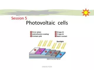
Electron Path • After a photon makes it's way through the encapsulate (glass or clear plastic) it encounters the antireflective layer. The antireflective layer channels the photon into the lower layers of the solar cell. • Once the photon passes the AR coating, it will either hit the silicon surface or the contact grid metallization. The metallization, being opaque, lowers the number of photons reaching the Si surface. The contact grid must be large enough to collect electrons yet cover as little of the solar cell's surface, allowing more photons to penetrate. • The photon's energy transfers to the valance electron of an atom in the n-type Si layer. That energy allows the valance electron to escape its orbit leaving behind a hole. a. Encapsulate b. Contact Grid c. The Antireflective Coating (AR Coating) d. N-Type Silicon e. P-Type Silicon f. Back Contact
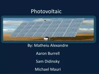
PV Formation Multiple modules can be wired together to form an array. In general, the larger the area of a module or array, the more electricity that will be produced. 2/3 of sun’s wavelengths= 1140nm Silicon band gap= 1.09 electron volts (which is smaller than 1140 nm) Silicon can capture most of solar photons.
How do you remove heat? In PV/T technology, the system removes and uses the waste heat through a convective airflow behind the PV panels. It can either be free air convective cooling or a forced flow scheme, but the latter consumes energy and reduces the net electrical gain of the system.
China Hotel Study • 260m2 (2340 ft2) wall proposed, on west side of building • Multi-framed mono-crystalline silicon modules mounted onto a 3m wide steel structure from 5th-28th level. Overall height=86.4m. • Each module= 36 silicon cells, yielded 18V at max. power point • Grouping of 30 panels/2 floor levels Fig. 2. Hotel building under study: (a) hotel tower with PV wall on west-facing facade, (b) layout of guest room floor.
Study Results The annual outputs from PV/C, PV/T, and BiPV differences are less than 1%, being at 83,680, 83,584, and 83,205 MJ, respectively. There’s no significant difference in electricity output. This is equal to about 2.32x10⁴ W The overall electrical efficiencies of all three in the year are ~10.2% In terms of annual electricity output, PV/C is marginally the best. PV/C has a simple design, greater effectiveness in reducing the space cooling energy consumption, and the resulting small improvement in the PV cooling performance. Therefore, would be the better choice. Fig. 4. Comparison of space heat gain via the PV wall for the period from May to October for four different designs.
Costs of PV • Unit energy costs: P= {(CT *[R/1 – (1-R)]-t) + ACO&M}/QA where: P=unit electricity cost, CT=total capital costs, R=discount rate, t=lifetime of the system, ACO&M=annual costs of operation and maintenance, and QA=annual output of the system. • A BiPV has an energy payback time of about 5.5 years. And are expected to have a lifetime of about 25 years. • Building-integrated systems offer cost reductions in both energy and economic, especially if the costs of avoided building materials are taken into account. • At current energy prices, PV power is uncompetitive with electric power by a factor of 3. But in 1972, PV electricity costs were 100x higher than they are now. • Worldwide PV = more than 1 GW (1 Billion Watts) in 1999 Use is increasing at 17% annual rate (4 yr doubling time) US Dept. of Energy forecasts 18% decrease in cost per doubling period. M. Oliver and T. Jackson
West Lafayette Irradiance • 7 yr ave.= 14.31MJ/m2 • Clear sky ave.=13.67 MJ/m2 • Ave. % penetrated through clouds=92% • Actual ave. solar E penetrated (irradiance)=13.16 MJ/m2 per yr • W.L. pop= 28,778 people, PU=38,847 total= 67,625 • U.S. pop=2.98x10⁸ • W.L. % of US pop= .000227 • (.000227)(3.5x10¹² W)= 7.95x10⁸ W This is the amount of energy used by West Lafayette • 7.95x10⁸ W / (153 W/m2)(.10)= 5.2x10⁵ m2 The area we would need to supply energy for W.L. via solar power 5.2x10⁵ m2= 52 km2= 12.96mi2 = 4.5x4.5mi
Conclusions • Would not be able to supply all of our electricity needs via photovoltaics, but could supply a fraction of the energy. • Is not yet competitive with primary energy sources, but price continues to lower. • Could definitely be a larger source of energy use in the future.
Sources • Chow, T. T.; Hand, J. W.; Strachan, P. A. Building - integrated photovoltaic and thermal applications in a subtropical hotel building. Applied Thermal Engineering (2003), 23(16), 2035-2049. CODEN: ATENFT ISSN:1359-4311. CAN 140:148974 AN 2003:647578 • M. Oliver and T. Jackson, Energy and economic evaluation of building-integrated photovoltaics. Energy 26 (2001), pp. 431–439. • S&S pp. 80-84 • http://www.census.gov/ • Pictures: NASA- http://science.nasa.gov/headlines/y2002/solarcells.htm US Dept. of Energy- http://www.eere.energy.gov/RE/solar_photovoltaics.html http://www.eere.energy.gov/solar_photovoltaics.html