Download
1 / 17
170 likes | 306 Views
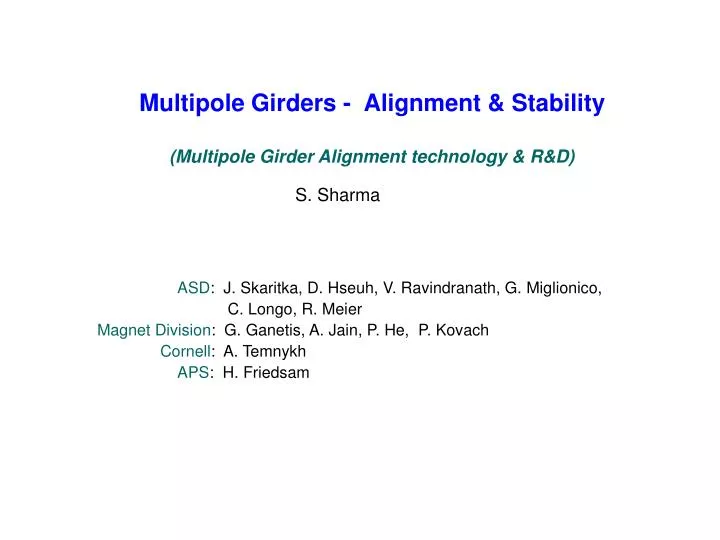
Multipole Girders - Alignment & Stability (Multipole Girder Alignment technology & R&D). S. Sharma. ASD : J. Skaritka, D. Hseuh, V. Ravindranath, G. Miglionico, C. Longo, R. Meier Magnet Division : G. Ganetis, A. Jain, P. He, P. Kovach

E N D
Multipole Girders - Alignment & Stability (Multipole Girder Alignment technology & R&D) S. Sharma ASD: J. Skaritka, D. Hseuh, V. Ravindranath, G. Miglionico, C. Longo, R. Meier Magnet Division: G. Ganetis, A. Jain, P. He, P. Kovach Cornell: A. Temnykh APS: H. Friedsam
Outline: • Alignment Technique and R&D • Reference Designs of the Magnets • Mechanical Stability of the Multipole Girders • Summary and Conclusions Multipole Girder with Stretched Wire
Magnet Alignment Technique Alignment tolerances: Magnets: 30 μm, 0.2 mrad Girders: 100 μm, 0.5 mrad Magnet alignment will be done with a vibrating wire alignment technique developed at the Cornell University by Prof. Alexander Temnykh.
Magnet Alignment Procedure • Accepted magnets and vacuum components shall be assembled (roughly aligned) on to the girder in an assembly station. • The girder assembly will be moved and installed into the temperature-controlled (± 0.1 ºC) alignment facility. • The girder will be aligned using a laser tracker. All electrical and water connections will be made to the magnets. • Magnet movers are installed beneath each magnet. • Magnet coils will be brought to their operating temperatures.
Magnet Alignment Procedure – contd. • A clean wire will be inserted through the vacuum chamber. • The wire will be secured to wire movers located at either end of the girder assembly and a controlled constant tension will be applied. • A Laser tracker will used to locate the two ends of the wire at the correct height relative to survey targets on the girder to within +/- 100 microns.
Magnetic Alignment Procedure – contd. • The magnets and the stretched wire shall be systematically powered. • Resultant wire vibration shall be monitored and analyzed. • The wire height can be adjusted vertically by the wire mover to correct for wire sag at each magnet location along the girder and can be reproducible to +/- 1 micron. • The magnet movers shall be used to locate the magnetic center of each quadrupole and sextupole to the wire to <25 microns
Vibrating Wire Technique - R&D Wire Mover Magnet Mover Experimental Setup (Magnet Division) • Magnets will be setup will be on an existing 15 ft. granite surface plate. • The wire movers will be mounted on two small separate granite surface plates on either side of the magnet setup. • The wire movers will be 22 ft. apart. • SLS magnets are on site. Design work to mount them on magnet positioners will begin soon.
Insulated V-notch Wire Photo Interrupters Small Dovetail Stages Targets Mirror Camera Lens Wire Finder Vibrating Wire Alignment R&D Wire Mover • Detailed design of major components are well under way. • Wire movers, magnet positioners and 3 Motorized X/Y Stages on order. • One set of 4 indicators with 1 um resolution is available. • Cornell data acquisition system has been duplicated.
Other end of wire on a table ~6m away RHIC spare Quadrupole X-Y Stage Lasers Digitalindicator Fixed end of wire pulley Photo Detectors weight Digitalindicator Vibrating Wire Alignment R&D – contd.
Girder Alignment • Approach: • (1) Use precise alignment mechanisms that are removable. • (2) Simple hardware to lock the components in place • stiff system with high natural frequencies. • lower and predictable thermal deformations.
Storage Ring Multipole Magnets Quadrupole Magnet Magnet designs must be robust. Field quality (harmonic contents) should remain within specified tolerances after repeated disassembly and reassembly. Several different designs (SPEAR, SLS, APS) are being evaluated. A 2-segment sextupole design is being developed.
Storage Ring Multipole Magnets Sextupole Magnet A 2-segment sextupole design is being developed.
Mechanical Stability of the Multipole Girders Tolerances on Magnets’ Motion • Thermal: relative thermal displacement between magnets on the same girder: < 0.025 μm. • Vibration: no magnification of ambient floor motion up to 50 Hz. • Below 4 Hz girder motions are highly correlated • Above 50 Hz the rms floor motion is < 0.001 μm
Thermal Deformations Magnets: Relative displacement on a girder: 0.01 μm Vacuum Chamber: Near fixed and flexible supports (SS plates): ~0.3 μm • Chamber deformations near the supports are ~ 0.17 μm with Invar plates. • BPMs need to be located near the fixed or flexible supports.
Displacement PSDs at locations near the NSLS-II site (Source: N. Simos) Ambient Floor Motion RMS Displacements at CFN ( 0.5-4) Hz : 200 nm (4-50) Hz : 20 nm (50-100) Hz : 0.4 nm
(b) (a) Natural modes of vibration for the girder-magnets assembly: (a) rolling mode = 63 Hz, (b) twisting mode = 79 Hz RMS (2-50) Hz Displacements: Floor: 20 nm Magnets: 21 nm Mode Shapes of the Girder-Magnets Assembly
Summary and Conclusions • The magnets on the girder will be aligned with a vibrating wire technique. • Girders will be aligned with precise but removable alignment mechanisms. • Reference designs for the SR magnets are being developed that are consistent with the vibrating wire alignment technique. • The multipole magnets-girder assembly (with removable alignment mechanism) will meet the stability specifications.