Download
1 / 48
500 likes | 683 Views
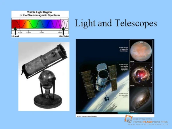
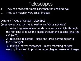
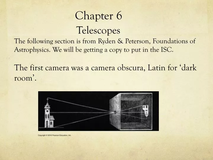
Chapter 6 Telescopes The following section is from Ryden & Peterson, Foundations of Astrophysics. We will be getting a copy to put in the ISC. The first camera was a camera obscura , Latin for ‘dark room’. . Types of Reflecting Telescopes. Here are the main types of reflecting telescopes.

E N D
Chapter 6 TelescopesThe following section is from Ryden & Peterson, Foundations of Astrophysics. We will be getting a copy to put in the ISC.The first camera was a camera obscura, Latin for ‘dark room’.
Types of Reflecting Telescopes • Here are the main types of reflecting telescopes
Quality of Images • Chromatic Aberration occurs in a very cheap, single component objective lens refractor when not all colors come to a focus.
Quality of Images • Spherical aberration occurs when the spherical surface of a lens or mirror does not bring all light rays to a focus. It affects refractors and reflectors.
Quality of Images • Coma is the aberration that occurs when light rays near the edge of a lens or mirror come to a focus at a larger distance from the optical axis than the center of the mirror. This is characteristic of off-axis images formed by parabolic mirrors.
Quality of Images • Here is a photographic example of coma. Coma is Latin for ‘hair’ and images with coma are fuzzy. The word comet comes from coma.
Quality of Images • The Ritchey-Chretien is a type of Cassegrain telescope that uses both primary and secondary mirrors that are hyperboloidal in shape, eliminating both spherical aberration and coma. CSM’s 20”telescope is of Ritchey-Chretien design.
Plate ScaleThis chapter is taken from ch 6, Foundations of Astrophysics by Ryden and Peterson. • One can compute the separation, d between a pair of stellar images on a chip when the stars themselves are separated by an angle q on the celestial sphere. This leads to s, the plate scale or image scale, s: s(arcsec/mm) = q(arcsec)/d(mm) (6.1)
Plate Scale If the angular separation between the two stars is small, we can use the small-angle approximation: where F is the telescope focal length and d is the distance between a pair of images on a chip. Or,
Plate ScaleConverting q(radians) to q(arc sec), we get eq 6.3, q(arc sec) = 206,265 (d/F)
Plate Scale • Here is how to get the image scale in terms of arcsec/mm – • Combining eqs 6.1 and 6.3, which are • s(arcsec/mm) = q(arcsec)/d(mm) (6.1) • q(arcsec) = 206,265 (d/F) (6.3) • we get, • s(arcsec/mm) = 206,265 (6.4) • F(mm)
Plate Scale • The smaller this value, s, the better detail on the image. For example, your eye has a focal length of ~ 17 mm and an image scale of s= 206,265/17 = 12,100 arcsec/mm or s=3.4o/mm when you look at the full moon. This image covers an area less than 0.15 mm across your retina.
Plate Scale • Astronomical telescopes have focal lengths expressed in meters, rather than millimeters. For these giant telescopes, we may write: • s(arcsec/mm) = 206.265 = 206.265 F(m) fD(m) where f is the focal ratio and D is the aperture in meters. Note 1: The comma in 206,265 has been replaced by a period to give 206.265. This is because the focal length is in meters, rather than in millimeters. Note 2: If f is the f/ratio and D is the diameter or aperture, the focal length, F = fD
Plate Scale • Example for the 40” refractor at Yerkes Observatory. • Aperture, D =1.02 m • Focal ratio, f = 19 • Plate scale of the Yerkes telescope is: • s = 206.265 = 10.6 arcsec/mm • 19(1.02)
Rayleigh Diffraction Limit • Image quality is limited by diffraction. When light from a point source passes through a circular aperture, diffraction produces an image that looks like a central bright disk surrounded by a series of alternating dark and bright rings.
Rayleigh Diffraction Limit • The diameter of the central disk, known as the ‘Airy disk’, after its discoverer, George Airy, is determined by the aperture, D and the wavelength, l of the observed light. Two point sources are said to be resolved when the center of the Airy disk of one source falls into the dark ring surrounding the Airy disk of the other source.
Rayleigh Diffraction Limit • This happens when the centers of the two light sources are separated by a distance • This is known as the Rayleigh diffraction limit. • qmin(rad) = 1.22 l D
Rayleigh Diffraction Limit • Observing at a l of 5000 A or 5 x 10⁻⁷ m, and resolving two stars separated by an angular distance q = 1” = 4.8 x 10⁻⁶ rad, requires a telescope of minimum diameter • D = 1.22 l q D = 1.22 (5 x 10⁻⁷m) = 0.13 m 4.8 x 10⁻⁶
Space Astronomy Misconceptions • There are three misconceptions wrt advantages of space-borne astronomy. • Misconception #1 •In space you can observe a celestial object continuously, not just at night. For a telescope in low Earth orbit (LEO), almost half of the celestial sphere is blocked by the Earth at any given time. Most objects can only be viewed for half an orbit at a time (45 minutes on, 45 minutes off).
Space Astronomy Misconceptions • Misconception #2 • The sky as seen from orbit is dramatically darker than the night sky on Earth. • Although the night sky is darker as seen from orbit, the improvement is not as great as what you might expect. At blue wavelengths, the sky is about half as bright as from the ground. Much of the sky background is due to sunlight scattered from interplanetary dust and distant unresolved stars and galaxies.
Space Astronomy Misconceptions • Misconception #3 • Observations from space are not affected by weather. The fact s there is ‘spaceweather’, generated by the sun and manifest in solar magnetic activity. Instruments and detectors deteriorate rapidly due to the harsh radiation environment and broad temperature range through which they are cycled.
Modern Observatory Telescopes • Large telescopes employ adaptive optics. In this technique, atmospheric wavefront distortions are sensed (by observing an artificial star) and compensating for these measured distortions by deforming the mirror with actuators.
Modern Observatory Telescopes • Why aren’t the largest telescopes mirrors monolithic? The answer is thermal inertia. To perform well, the mirror must be at the same temperature as the air around it. If the mirror is warmer than its surroundings, the mirror will radiate infrared light, heating the air above the mirror and causing turbulence and poor seeing.
Thermal Inertia • Thermal inertia is the measure of a mirror to store heat during the day and radiate it away at night. It scales with mass and the mass of a conventional mirror scales as D3, since the thickness must increase proportionately with diameter, to keep the mirror stiff.
Beating Thermal Inertia • Multiple mirrors – A large effective collecting area can be achieved by combining the light collected by smaller individual mirrors. An example is the Large Binocular telescope (LBT) which has two 8.4 m mirrors.
Beating Thermal Inertia • Another example is the VLT telescope in Cerro Paranal Chile. It consists of 4 telescopes, each with 8.2 m mirrors. They can work separately or combined, using interferometry.
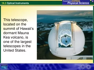
Beating Thermal Inertia • Segmented mirrors – Instead of a monolithic mirror made from a single slab of glass, a mirros can be made of many segments kept aligned through computer controlled active supports. The two 10 m Keck telescopes on Mauna Kea are prime examples. Each mirror consists of thirty-six 1 meter segments.
Beating Thermal Inertia • Honeycombed mirrors – In this type of mirror, glass is melted over heat resistant ceramic forms that leave the back of the mirror with a honeycomb structure that is stiff but still lightweight. The two mirrors of the LBT are made this way. (Birds’ bones have a similar internal structure, which is why they are so light but very stiff).
Seeing • The quality of the image of a stellar point source at a given observing location at a specific time is know as seeing. Due to Earth’s turbulent atmosphere, local changes in atmospheric temperature and density over distances ranging from centimeters to meters create regions where the light is refracted in random directions. This causes the image of a point source, such as a star to become blurred or ‘twinkle’.
Seeing • Some of the best seeing is at Mauna Kea Observatory at 13, 800 feet above sea level. The seeing is routinely between 0.5” and 0.6” 50% of the time. On the best nights, it can be 0.25”! • Other great observatory sites are • Kitt Peak National Observatory in Tucson, Az. • Tenerife and La Palma on the Canary Islands • Cerro Tololo Inter-American Observatory in the Chilean Andes
Seeing • Why don’t planets twinkle? • Stars are point sources and are affected by our turbulent atmosphere, causing them to twinkle. However, a planet’s larger angular size make them larger than the scale of atmospheric turbulence. Distortions are averaged out over the size of the image. The result is that planets don’t twinkle! • The exception occurs when a bright planet is viewed as it rises or sets. One then looks through a very turbulent atmosphere and distortions do not average out, leading to twinkling.
Radio Telescopes (from BOB) • The strength of a radio source is measured in terms of the spectral flux density, S(n), which is the amount of energy per second, per unit frequency interval striking a unit area of the telescope. To determine the total amount of energy per second (the power) collected by the receiver, the spectral flux must be integrated over the telescope’s collecting area and over the frequency interval, for which the detector is sensitive, which is the bandwidth.
Radio Telescopes • If the efficiency of the detector at a frequency n, is denoted by fn, then the amount of energy detected per second becomes
Radio Telescopes • If the detector is 100% efficient over Dn, meaning that fn =1, and if S(n) is constant over that interval, then the integral reduces to P = SA Dn. • A is the area of the radio dish. • A typical radio source has a spectral flux density on the order of one jansky (Jy), where 1 Jy = 10-26 W M-2 Hz -1. Spectral flux densities are usually pretty weak ~ several mJy. Large dishes are necessary to receive such weak signals.
Radio Telescopes • Example 6.3.1 • Cygnus A is the third strongest radio source, after the Sun and Cassiopeia A. At 400 MHz (a wavelength of 75 cm), its spectral flux density, S(n), is 4500 Jy. Assuming that a 25 m diameter radio telescope is 100% efficient and is used to receive the radio energy of Cygnus A over a bandwidth of 5 MHz, the power detected by the receiver is: • P = S(n) p (D/2)2Dn
Radio Telescopes • P = S(n) p (D/2)2Dn where • S(n) = 4500 x 10-26 Wm-2Hz-1 • D = 25 m • Dn= 5 x 10⁶Hz • we have that, • P = 4500 x 10-26 Wm-2Hz-1p(25/2)2m2 5 x 10⁶ Hz • P = 1.10 x 10⁻¹³ W
Improving Resolution of Radio Telescopes • Rayleigh’s criterion when applied to radio telescopes shows that resolution in the radio domain is much worse than optical telescopes, due to the much longer nature of radio waves. To obtain comparable resolution, much larger dish diameters are needed.
Improving Resolution of Radio Telescopes • Example 6.3.2 • To obtain a resolution of 1” at a wavelength of 21 cm, the dish diameter must be: In order to resolve an object 1” in diameter, a radio telescope dish must be 52.8 km in diameter! The largest radio telescope is that at Arecibo Observatory in Puerto Rico. Its diameter is 300 m or 1000 ft.
InterferometryA way to get higher resolution is to use a technique called interferometry. Shown, is fig.6.22.
Interferometry Figure 6.22 shows two radio telescopes separated by baseline, d. Since the distance from scope B to the source is greater than the distance of scope A from the source by an amount L, a specific wavefront will arrive at B after it has arrived at A. If the two signals are in phase, their superposition will result in a maximum if L is equal to an integral number of wavelengths. In this case, L = nl, where n = 0, 1, 2, … and we have constructive interference. Similarly, if L is an odd number of wavelengths, L = (n--1/2)l, where n= 0, 1, 2…, we have destructive interference.
Interferometry • The pointing angle q is related to d and L by • Sin q = L/d • By combining the signals from two radio telescopes, one can determine the position of the source by using the interference pattern produced by these scopes.
Antenna Pattern • Here is the pattern produced by a single antenna. The narrowness of the main lobe is characterized by the half-power beam width. The width can be decreased and the side lobes reduced by the addition of more scopes.
VLA • The Very Large Array or VLA consists of 27 radio telescopes in a movable Y configuration with a maximum configuration diameter of 27 km. Each dish has a diameter of 25 m.
Atmospheric Windows • Our atmosphere blocks several regions of the EM spectrum from the ground. Below is transparency of Earth’s atmosphere as a function of wavelength.
Atmospheric Windows • Since water vapor is the chief absorber of IR radiation from the ground, IR observations have to done in space. Notable orbiting IR telescopes are: • IRAS, 0.6 m in diameter, launched in 1995, cooled by liquid helium and operation ceased in 1998, due to He depletion. • Spitzer Space Telescope, 0.85 m, f/12 mirror made of beryllium, cooled to less than 5.5 K. Still operational.