Download
1 / 47
480 likes | 650 Views
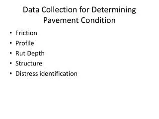
PAVEMENT VISUAL ASSESSMENT Handheld Data Collection Devices and Laser Road Imaging System. Paul Olivier Bob Briggs SAT WORKSHOP 24 August 2010. OUTLINE. Introduction Handheld Data Collection Devices Laser Road Imaging System. INTRODUCTION. Why Handheld Data Collection Devices?

E N D
PAVEMENT VISUAL ASSESSMENTHandheld Data Collection DevicesandLaser Road Imaging System Paul Olivier Bob Briggs SAT WORKSHOP 24 August 2010
OUTLINE • Introduction • Handheld Data Collection Devices • Laser Road Imaging System
INTRODUCTION • Why Handheld Data Collection Devices? • Paper based systems have potential errors when performing data capture • Location referencing • No street names • Disorientation Incorrect condition assessment for a particular link
INTRODUCTION (...contd) • We have used 3 types : • Rugged PC (2003) • Laptop (2008) • Juno (2010)
LRIS – Laser Road Imaging System Robert C Briggs, P.E. Dynatest Consulting, Inc. Starke, FL
INTRODUCTION To achieve the goal of automated crack detection an ideal imaging system should have the following features: • It needs to be immune to the variable illumination conditions caused by the sun. • It needs to be immune to shadows cast from road side objects such as trees, buildings, viaducts and the inspection vehicle itself. • The system should be able to operate in both daylight and at night. • The artificial light source should provide a uniform illumination over the entire image. • The system should be set up in order to maximise the contrast of the crack images. • The resolution of the images should be 1mm or better. • The system should use a minimal amount of power.
Halogen vs Laser illumination Halogen vs Lasers Sun/shadow immunity Depends Yes Day/night operation Yes Yes Uniform illumination No Yes Crack image contrast Low High Needed power 20000 W 200 W
Linescan detector array LRIS – Optical configuration Collection lens Laser line projector Laser plane Laserline a