Download
1 / 21
250 likes | 494 Views
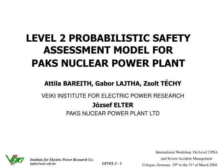
LEVEL 2 PROBABILISTIC SAFETY ASSESSMENT MODEL FOR PAKS NUCLEAR POWER PLANT. Attila BAREITH, Gabor LAJTHA, Zsolt TÉCHY VEIKI INSTITUTE FOR ELECTRIC POWER RESEARCH József ELTER PAKS NUCEAR POWER PLANT LTD. Content. Introduction Scope of Level 2 PSA

E N D
LEVEL 2 PROBABILISTIC SAFETY ASSESSMENT MODEL FORPAKS NUCLEAR POWER PLANT Attila BAREITH, Gabor LAJTHA, Zsolt TÉCHY VEIKI INSTITUTE FOR ELECTRIC POWER RESEARCH József ELTER PAKS NUCEAR POWER PLANT LTD
Content • Introduction • Scope of Level 2 PSA • Interface with Level 1, grouping of sequences • Accident progression and containment analysis • Containment Event Trees • Conditional Probability of Nodes • Release Categories • Accident management • Results
Level 2 PSA • 3 years work (2000-2003) • Preparation of models, connection between Level 1 and 2 PSA • Level 2 PSA for the present status of the plant • Level 2 PSA with assumption of accident management strategies • KFKI Atomic Energy Research Institute (AEKI) • VEIKI Institute for Electric Power ResearchCo • Paks NPP Co. • ABS Consulting Co. was responsible for the fragility curve calculations. The starting point of the Level 2 PSA is the Level 1 PSA study. The existing Level 1 PSA covers accident • internal initiating events emerging at shutdown states • spent fuel storage pool (SFSP) events • internal initiating events and internal hazards as fire and flooding at nominal power This is the scope of the Level 2 PSA study
Interface with Level 1, grouping of sequences • reactor core status reactor pressure at the onset of core damage type and amount of emergency cooling before and during core damage • status of the containment systems containment initial leakage rate, isolation failure, structural damage, primary to secondary leakage (PRISE), by-pass availability of containment systems (spray, bubbler condenser trays, recirculation and ventilation systems)
ACCIDENT PROGRESSION AND CONTAINMENT ANALYSIS • Type of code: MAAP4/VVER code developed from the original MAAP code by Westinghouse (WESE) • MAAP provides an integrated framework for evaluating the timing of key accident events, thermodynamic histories of the reactor coolant system, core and containment, and corresponding estimates of fission product release and transport. • Supplemented with calculations performed with CONTAIN, H2AICC, VESSEL, MVITA, ICARE
ACCIDENT PROGRESSION AND CONTAINMENT ANALYSIS (cont’d) • Phenomena within the RPV • core-heat-up and degradation • zirconium oxidation • fission product release from fuel and transport in primary circuit • core degradation and loss of geometry • vessel melt-through • Phenomena within the reactor cavity • debris ejection from vessel, direct containment (cavity) heating • debris structure heat transfer (cavity door) • high pressure melt ejection (fission product release) • ex-vessel core-coolant interaction • steam explosion • core-concrete interaction • Phenomena within the containment building VVER-440/213 specific containment thermal-hydraulics (pressurisation) hydrogen combustion engineered safety features (spray system) transport of fission products (bubble condenser, spray, leak)
Containment Event Trees CET structure and nodal questions: • Represented by 3 different time regimes • Questions - Early phase • Temperature induced failure of the primary coolant system • Reactor cavity flooded • Melt progression arrested • Spray system recovery • Hydrogen management • Hydrogen burn • Containment failure mode
Containment Event Trees(Cont’d) • Questions - Intermediate phase • High Pressure Melt Ejection (HPME) • RPV failure: pour • Steam explosion • Containment failure mode • Questions - Late phase • Molten Core Concrete Interaction • Cavity door failure • Spray system recovery • Hydrogen burn • Filtered vent (open, close) • Containment failure mode
Hydrogen Burn • Hydrogen production (MAAP calculation for each sequence) • Hydrogen distribution in each volume (H2. CO, O2, CO2, H2O mole fraction, pressure, temperature versus time) – from MAAP calculation • Combustion mechanism – three combustion mechanisms are distinguished (burn and Deflagration Detonation Transition), for the determination of containment pressure load the H2AICC code is used with Modified Adiabatic Isochoric Complete Combustion (AICC) model • Pressure load due to hydrogen burn • hydrogen deflagration - HBURN code calculated pressure versus time • DDT - time frame and probability based on Sherman- Berman conditions
Calculated Pressure Load Due to Hydrogen Burn in-vessel ex-vessel
Containment Failure due to Hydrogen Burn • Determination of the probability of Ignition – • probability of ignition depends on the existence of igniting sources and also on the hydrogen concentration, duration of different hydrogen concentrations (recombiner) • Determination of the probability of pressure load
Containment Failurenodal question for containment failure due to hydrogen burn Joint treatment of containment loads and fragility curves Density function of the pressure load probability: f(p), distribution function: F(p). The probability of the containment damage is described by the fragility curve: Frag(p) = P(pfail < p) The Containment Failure Probability for the entire load pressure range is CFP = integral dp f(p) Frag(p) = integral dp f(p) • integral dp` frag(p`)
Conditional Probability of CET Nodes • Temperature induced hot leg failure for high pressure sequences -MAAP calculation – failure was considered but it was not taken into account, conservative assumption • Core melt arrested -recovery time was assumed with an exponential distribution • Containment failure due to hydrogen burn - calculated • Cavity failure due to DCH -cavity pressure calculated by CONTAIN code, • Cavity door seal failure - expert judgement based on VESSEL code and hand calculations • Containment overpressurization - calculated, comparison of the calculated pressure and fragility curve • Steam explosion - based on expert judgementtaking into account available water mass and corium, corium temperature (superheated, saturated), water temperature (saturated, subcooled)
Release Categories • MAAP calculates the fission product release and transport (from fuel to environment) • Grouping of fission products (release time, height) • Binning of event tree and states into release categories
A004 hermetization (Mitigating of the effect of the Cavity Door Failure)
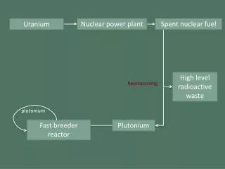
water injection line Ventillation line Isolation and radiation shield (in lower position) Cavity Flooding External cooling of the reactor pressure vessel
Conclusion • Effective Reduction of Early Containment Failure Probability • due to hydrogen management • Effective Reduction of Late Containment Leak Probability • due to A 004 compartment hermetization orcavity flooding) • Effective reduction of basemat melt through • due to cavity flooding