Download
1 / 9
90 likes | 157 Views
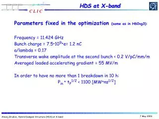
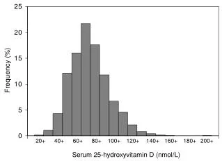
Low Vg a/ λ =0.16. High Vg a/ λ =0.19. So why?. The first cell puzzle….

E N D
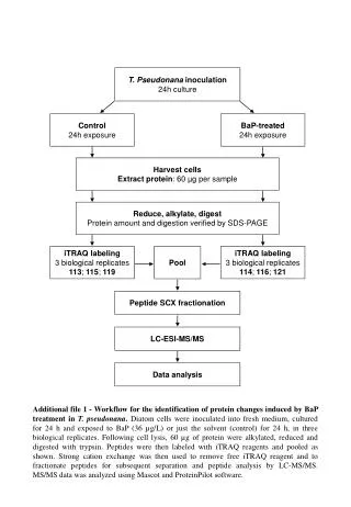
Low Vg a/λ=0.16 High Vg a/λ=0.19 So why? The first cell puzzle… Very often we do observe, that after accelerating structure processing the most of the surface modifications take place in a few first cells. Also the number of cells involved is correlated with the group velocity, the less the Vg the fewer cells modified. As one of the conventional explanation one could expect the statistical distribution of the events in a chain model. However with adopted processing strategy (trip rate ~10-3) the event probability and normalized to that damage distribution is calculated to be very flat. HDS 60 (cells) copper was processed from both sides HDS 60 HDS 11 titanium
- The breakdown initiation • The RF pulse dependence • The damage mechanism • and … will not be addressed What do we certainly know, the breakdown ignition is a very fast process: 0.1 -10 ns. If so, one can propose the main difference between the “first” and “second” cell is accessible bandwidth. And the lower group velocity the more the difference. The first cell, if breakdown occurs is loaded by the input coupler/waveguide and is very specific in terms of bandwidth. Other words, the first cell can accept “more” energy during breakdown initiation then consequent ones. Worse to mention that we do not know the exact transient behavior of the breakdown and the structure bandwidth could play important role.
Breakdown ‘naive’ modeling in HFSS Structure: 2pi/3 aperture 3.5 mm (Vg=4.5%) Radiation spectra (breakdown in cell#1 ) Missing energy plot To the input coupler Pout RF current source Iejwt To the output coupler Pin = 50MW Ib, kA/mm2 F, GHz
Configuration #1 (breakdown resonant fuse) : Resonant cavity with reduced electric surface field (HO1) is located between structure and waveguide. Standing wave S-parameters, dB F, GHz Traveling wave
1-st cell Configurations #... Inline taper with increased stored energy Vg=PLc/W Stored Energy/cell P/W NLC inline taper Cell # Cell # V. Dolgashev (May 2002) Inline taper with a “speed” bump Stored Energy/cell Vg=PLc/W Cell # Cell # R. Zennaro (June 2007)
TWO FREQUENCY STRUCTURE Type 1 Type 2 Transversely “0” Transversely “pi”
Transverse Ez (t) distributions Type 1 Type 1