Download
1 / 24
240 likes | 394 Views
GOCE Workshop. SATELLITE TO SATELLITE TRACKING INSTRUMENT DESIGN PERFORMANCE. HERITAGE. SSTI instrument is based on the LAGRANGE receiver architecture LAGRANGE receiver development started in 1998 with Alcatel Alenia Space Italia S.p.A. internal funds

E N D
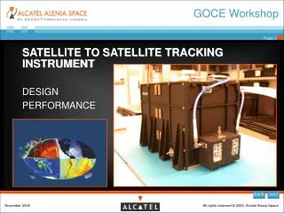
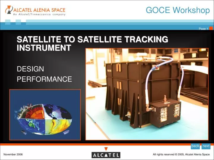
GOCE Workshop • SATELLITE TO SATELLITE TRACKING INSTRUMENT • DESIGN • PERFORMANCE
HERITAGE • SSTI instrument is based on the LAGRANGE receiver architecture • LAGRANGE receiver development started in 1998 with Alcatel Alenia Space Italia S.p.A. internal funds • The product is developed, manufactured and tested by the Navigation Department in Milan plant • LAGRANGE X-prototype developed in 1999 with ASI contribution for demonstrative flight on SAC-C satellite • LAGRANGE fully space compatible design completed end 2001 • LAGRANGE is onboard the following satellites: • RADARSAT-2 (2 FM’s) • COSMO SKYMED constellation: 3 satellites (1 EQM + 6 FM’s) • OCEANSAT (1 EM + 1 FM tailored for Radio Occultation application) • Soyuz (1 FM) • LAGRANGE was onboard Soyuz mission 10S in April 2005 in the frame of ENEIDE mission
DESIGN 1/3 Receiver Type: Integrated GPS receiver for spaceborne applications Channels: 12 dual-frequency channels Frequency Band: GPS L1: 1575.42 MHz GPS L2: 1227.6 MHz Observables: L1CA, L1P & L2P Code phase L1CA & L2P Carrier phase L2-L1 delta range Instantaneous Doppler Time
DESIGN 2/3 • Receiver Unit: • Power Supply Module • Processor Module • AGGA 2 Module • RF/IF Module • Synch Module • Motherboard • RYMSA • GPS L1/L2 Antenna
MAIN FUNCTIONALITY Pseudorange measurements (Code Phase) • C/A Code, for GPS L1 • P Code, for GPS L1 & L2 • L1P - L2P Delta Range Integrated Doppler measurements (Carrier Phase) • L1 and L2 Carrier Phase Signal and Noise measurements • Signal to Noise Ratio C/No in dB/Hz units evaluated at the tracking loop input • AGC Setting Real-Time Orbit Determination, determined using GPS C/A signal observations and navigation messages (PVT solution through SPS and Navigation Kalman Filter) Time measurements, determined from the GPS system
ELECTRICAL INTERFACES POWER LINES: • N° 1 Unregulated Primary Power Supply Interface (connected to Satellite Power Bus) TELECOMMANDS: • N° 8 High Power ON/OFF Command (HPC) (Nom + Red for Receiver ON, Nom + Red for Receiver OFF, Nom + Red for Watch Dog Enabling, Nom + Red for Watch Dog disabling) TELEMETRY: • N° 2 MIL-STD-1553B I/F (Nominal + Redundant) • N° 1 Temperature Sensing Monitor I/F (TSMN) (Thermistor on the DC/DC Board) • N° 1 Analog Single Ended Monitor (ASMN) (5V Secondary Voltage Monitor) • N° 2 Relay Sensing Monitor (RSMN) (Unit ON/OFF and Watch-Dog EN/DIS Relays) SYNCHRONISATION: • N° 2 External Synchronization Pulse Per Second (PPS) (Nominal and Redundant) RF INTERFACE: • N° 1 RF Input (from Antenna)
PHYSICAL BUDGETS Mechanical Dimensions • 250 mm x 200 mm x 190 mm (LxHxW) including mounting feet • 29.32 mm x 212.1 mm x 225.5 including Diplexer & LNA Cables Mass: • Receiver Unit : 5.35 Kg ± 5% • Antenna: 490.6 g ± 10% • Cable to antenna: 225g ± 10% Power Consumption: • 29.3 W (steady state) • 32.1 W (OCXO warm-up)
SSTI PERFORMANCE SSTI Characteristics • Tight requirements in order to comply with system specifications • Performance Requirements on three large areas: • Real-Time Navigation (PVT) • Raw Measurements (errors, acquisition/tracking thresholds, biases…) • Robustness • Temperature Sensors on-board placed on sensitive points of the RF board in order to allow calibration of Rx-specific biases (IFB) • Precise Modeling/Testing of errors (Multipath, antenna CoP etc.) • Peculiar measurement sampling procedure (sample after PPS in input), typical of timing receivers • Freely drifting Rx time scale, Rx bias bound between ± 10 ms
SSTI PERFORMANCE SSTI Performance Test Setup:
SSTI PERFORMANCE • RT Navigation • Tested under Selective Availability ON and OFF (major source of RT navigation error) • Output tested in different reference frames (ECI J2000, ECI TOD, ECEF) • Orbital GOCE scenario, usually having a duration of 12 hours • Period of time representative of GPS orbital period • GOCE orbit modeled using a 70x70 gravity field model, GPS 8x8 • Drag acceleration enabled • Force model and reference frame basically limited by Spirent implementation.
SSTI PERFORMANCE • RT Navigation Scheme
SSTI PERFORMANCE • Navigation Requirements: Navigation Results: Results with S/A off (current GPS status) much better: NKF Position J2000.0 (3D 3s): ~ 30.35 m NKF Velocity J2000.0 (3D 3s): ~ 0.12 m/s
SSTI PERFORMANCE • Navigation Results (example)
SSTI PERFORMANCE • Visibility to GPS (example) Direction Of Arrival Density Plot
SSTI PERFORMANCE • Acquisition-Tracking thresholds & Measurements accuracy:
SSTI PERFORMANCE SSTI Sensitivity to Ionospheric Scintillation • A dedicated test campaign has been carried out to check robustness against ionospheric scintillation activity • Ad-hoc test set-up (Test Equipment, SSTI firmware modifications) • GISM (Global Ionospheric Scintillation Model) simulator by IEEA has been used to generate the scintillation time series in terms of amplitude and phase errors • Amplitude fades injected at RF level using a programmable RF attenuator • Phase errors injected at DSP level in the SSTI (pre-correlators carrier rotation) • Orbital scenario in the RF simulator, scintillation error applied repeatedly during a pass. • S4 values from 0 (no effect) up to 0.8. GISM version has S4 & sigma_phi linked • Analyses in terms of loss of lock on carrier phase in post-processing
SSTI PERFORMANCE Ionospheric Scintillation Test Setup Test Setup Phase error injection
SSTI PERFORMANCE Scintillation Time Series Example of amplitude and phase errors applied: Characterization in terms of loss of lock sensitivity to S4 parameter
SSTI PERFORMANCE Example of Results S4 = 0.76: Not OK! S4 = 0.6: OK! SUMMARY:
SSTI precursor: ENEIDE • SSTI-Like experience on ENEIDE experiment (May 2005): • different target application (combined GPS/EGNOS/WAAS tracking from space) but same technological base of SSTI • LAGRANGE receiver installed inside the Soyuz Orbital Module • GNSS antenna installed outside the Soyuz vehicle • Laptop installed inside the Orbital Module and connected with LAGRANGE Receiver via MIL-BUS1553 data cable • The Crew MMI provides commanding and monitoring functions • All the data acquired by LAGRANGE Receiver handled by the Laptop Software and stored on the PCMCIA Hard-Drive
SSTI precursor: ENEIDE ENEIDE experiment antenna LAGRANGE receiver T. Col. Vittori ENEIDE Experiment Conductor
SSTI precursor: ENEIDE All the analyses conducted on the flight data allow to say that the ENEIDE experiment was carried out successfully. ENEIDE proved to be a benchmark for the validation of the AAS-I receivers of LAGRANGE class, like GOCE SSTI. The different environmental conditions in which the receiver operated (Sun-pointing attitude, orbital attitude, peculiar antenna pointing constraints etc.) made the experiment an important laboratory for different applications like attitude analysis, atmospheric sounding, space weather, real-time navigation and control. • Reference: • A. Zin, S. Landenna, A. Conti, L. Marradi, M. S. Di Raimondo, “ENEIDE: an Experiment of a Space-borne, L1/L2 Integrated GPS/WAAS/EGNOS Receiver”, European Navigation Conference 2006, (ENC 2006), May 08-10 2006, Manchester, UK.
GOCE SSTI: FACTS • State-of-art GPS space receiver technology • Advanced performance • Twelve LAGRANGE flight models built (two SSTI FMs) • Fully qualified for space applications for several satellites • Flight proven