Download
1 / 27
520 likes | 1.41k Views
Prof. Shamik Sengupta Office 4210 N ssengupta@jjay.cuny.edu http://jjcweb.jjay.cuny.edu/ssengupta/ Fall 2010. Lecture 3 Wireless Channel Propagation Model. What have we covered in last 2 lectures. An overview of wireless technologies Evolution of wireless Basic Cellular concept

E N D
Prof. Shamik Sengupta Office 4210 N ssengupta@jjay.cuny.edu http://jjcweb.jjay.cuny.edu/ssengupta/ Fall 2010 Lecture 3 Wireless Channel Propagation Model
What have we covered in last 2 lectures • An overview of wireless technologies • Evolution of wireless • Basic Cellular concept • The hexagon “cell” concept • Frequency reuse • Today, we will cover • Basic concepts of wireless communications and • Wireless channel propagation models
Wireless Communication • What is wireless communication? • Basically the study of how signals travel in the wireless medium • To understand wireless networking, we first need to understand the basic characteristics of wireless communications • How further the signal can travel • How strong the signal is • How much reliable would it be (how frequently the signal strength vary) • Indoor propagation • Outdoor propagation and • Many more… • Wireless communication is significantly different from wired communication
Wireless Propagation Characteristics • Most wireless radio systems operate in urban area • No direct line-of-sight (los) between transmitter and receiver • Radio wave propagation attributed to • Reflection • Diffraction and • Scattering • Waves travel along different paths of varying lengths • Multipath propagation • Interaction of these waves can be constructive or destructive Reflection (R), diffraction (D) and scattering (S).
Wireless Propagation Characteristics(contd.) • Strengths of the waves decrease as the distance between Tx and Rx increase • We need Propagation models that predict the signal strength at Rx from a Tx • One of the challenging tasks due to randomness and unpredictability in the surrounding environment Pr v Pt d=vt
Wireless Propagation Models • Can be categorized into two types: • Large-scale propagation models • Small-scale propagation models • Large-scale propagation models • Propagation models that characterize signal strengths over Tx-Rx separation distance • Small-scale propagation models • Characterize received signal strengths varying over short scale • Short travel distance of the receiver • Short time duration
Fast Very slow Wireless Propagation Models (contd.) • Large-scale propagation • Small-scale propagation Pr/Pt Pt Pr v d=vt d=vt
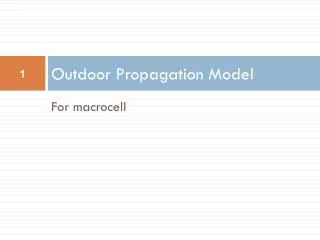
Large-scale propagation model • Also known as Path loss model • There are numerous path loss models • Free space path loss model • Simple and good for analysis • Mostly used for direct line-of-sight • Not so perfect for non-LOS but can be approximated • Ray-tracing model • 2-ray propagation model • Site/terrain specific and can not be generalized easily • Empirical models • Modeled over data gathered from experiments • Extremely specific • But more accurate in the specific environment
Free space Path Loss Model • What is the general principle? • The received power decays as a function of Tx-Rx separation distance raised to some power • i.e., power-law function • Path loss for unobstructed LOS path • Power falls off : • Proportional to d2
Free space Path Loss (contd.) • What is the path loss? • Represents signal attenuation • What will be the order of path loss for a FM radio system that transmits with 100 kW with 50 km range? • Also calculate: what will be the order of path loss for a Wi-Fi radio system that transmits with 0.1 W with 100 m range?
Path Loss in dB • It is difficult to express Path loss using transmit/receive power • Can be very large or • Very small • Expressed as a positive quantity measured in dB • dB is a unit expressed using logarithmic scale • Widely used in wireless • With unity antenna gain,
dBm and dBW • dBm and dBW are other two variations of dB • dB references two powers (Tx and Rx) • dBm expresses measured power referenced to one mW • Particularly applicable for very low received signal strength • dBW expresses measured power referenced to one watt • dBm Widely used in wireless • P in mW • In a wireless card specification, it is written that typical range for IEEE 802.11 received signal strength is -60 to -80 dBm. What is the received signal strength range in terms of watt or mW?
Relationship between dB and dBm • What is the relationship between dB and dBm? • In reality, no such relationship exists • dB is dimensionless • dB is 10 log(value/value) and dBm is 10 log (value/1miliwatt) • However, we can make a quick relationship between dBm and dBW and use the concept wisely!
Back to Path Loss model • We saw Path loss expressed in dB • Note, the above eqn does not hold for d=0 • For this purpose, a close-in distance d0 is used as a reference point • It is assumed that the received signal strength at d0 is known • Received signal strength is then calculated relative to d0 • For a typical Wi-Fi analysis, d0 can be 1 m.
Back to Path Loss model (contd.) • The received power at a distance d is then • In dBm,
Numerical example • If a transmitter transmits with 50 W with a 900 MHz carrier frequency, find the received power in dBm at a free space distance of 100 m from the transmitter. What is the received power in dBm at a free space distance of 10 km?
Path Loss Model Generalized • In reality, direct LOS may not exist in urban areas • Free space Path Loss model is therefore generalized • n is called the Path Loss exponent • Indicates the rate at which the Path Loss increases with distance d, obstructions in the path, surrounding environment • The worse the environment is the greater the value of n
Path Loss Model Generalized (contd.) • Generalized Path Loss referenced in dB scale • Received signal strength referenced in dBm scale
Path Loss Example • Consider Wi-Fi signal in this building. Assume power at a reference point d0 is 100mW. The reference point d0=1m. Calculate your received signal strength at a distance, d=100m. Also calculate the power received in mW. Assume n=4. • This is a typical Wi-Fi received signal strength.
Indoor Propagation Model • The indoor radio channel differs from the traditional mobile radio channel in outdoor • Distances covered are much smaller • Variability of the environment is much greater • Propagation inside buildings strongly influenced by specific features • Layout and building type • Construction materials • Even door open or closed • Same floor or different floors • Partition Losses
Partition Losses • Partition Losses • Same floor • Between floors • Characterized by a new factor called Floor Attenuation Factors (FAF) • Based on building materials • FAF mostly empirical (computed over numerous tests) • For example, • FAF through one floor approx. 13 dB • Two floors 18.7 dB • Three floors 25 dB and so on…
Cellular Model (signal to interference) • From the propagation model, • Let’s combine today’s concept with last week’s cellular concept • Let’s find out signal to interference • In a cellular radio system with 7-cell reuse pattern and a 6 co-channel interferers, what is the signal to interference in dB? Assume Path loss exponent = 4. Q: co-channel Reuse ratio m co-channel interferer Cell radius R Co-channel interferer distance Di
Numerical example (signal to interference) • In a cellular radio system, the required signal to interference must be at least 15 dB. What should be the cluster size (N) if Path loss exponent = 3. Assume 6 co-channel interferers. • Soln hint: Let’s assume N =7 To convert it to dB, do 10log(16.04) = 12.05 dB This is still less than reqd 15 dB. So we need to use a larger N. Try for next feasible N.
Mobile Radio Propagation: Small scale fading • What is small-scale fading? • In contrast to large-scale propagation we studied so far • Small-scale fading describe rapid fluctuation of the signal over • short period of time and/or • short travel distance Pr v Pt d=vt
Factors influencing small-scale fading • Multipath propagation • Interference between two or more versions of the transmitted signal • Arrive at the receiver at slightly different times • Speed of the Mobile • Relative motion between Base Station and the mobile • Signals travel varying distances • Speed of the surrounding objects • Typically this can be ignored if the obstacles are fixed • May not be so in a busy urban area