Download
1 / 22
220 likes | 324 Views
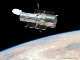
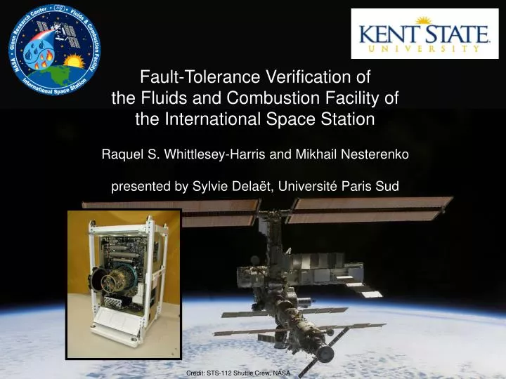
Fault-Tolerance Verification of the Fluids and Combustion Facility of the International Space Station Raquel S. Whittlesey-Harris and Mikhail Nesterenko presented by Sylvie Dela ë t, Universit é Paris Sud. Credit: STS-112 Shuttle Crew, NASA. Outline.

E N D
Fault-Tolerance Verification of the Fluids and Combustion Facility of the International Space Station Raquel S. Whittlesey-Harris and Mikhail Nesterenko presented by Sylvie Delaët, Université Paris Sud Credit: STS-112 Shuttle Crew, NASA
Outline • Introduction to FCF andProject Motivation • space environment description • applying stabilization to FCF • using model checking in stabilization verification • Architecture & Operation • FCF SPIN Model • Experiments • Impact & Future Work
The Fluids and Combustion Facility • Permanent installation onboard the International Space Station (ISS) US laboratory module • Two racks • Combustion Integrated Rack (CIR) • Facilities for combustion science experiments • Multi-user Droplet Combustion Apparatus • Fluids Integrated Rack (FIR) • Facilities for fluid physics experiments • Light Microscopy Module
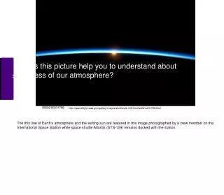
Why Fault-Tolerance for FCF • Adverse environment • harsh acceleration forces • launch (3-g) and re-entry (1.5-g) • microgravity (ug) vibrations • e.g., orbital maneuvers, experimental vibrations • radiation • South Atlantic Anomaly • Protection of life, equipment – care must be taken to prevent contamination of ISS and experiment environments • Limited access • crew time limited • currently no more than 1.5 hours per month • experiment access via Telescience • available approximately 30% of the time
Why Self-Stabilization • Faults are numerous and unpredictable in nature and effect, resources are limited, safety is critical • FCF specification • requires FCF to tolerant a single component failure regardless of cause • stricter requirements in future • A system is self-stabilizing if, starting from an arbitrary state, it is guaranteed to arrive at legitimate state and behave correctly afterwards • a fault may take the system into an arbitrary state • self-stabilization guarantees recovery regardless of fault cause • Self-stabilization is well-suited for FCF fault-tolerance design
Why Use Model Checking • Traditionally self-stabilization is proven analytically: • determine invariant guaranteeing correct behavior • show that system starting from arbitrary states eventually satisfies this invariant • Complex practical systems such as FCF have a large number of possible states and special cases • analytical proofs for such systems are • difficult to construct • cumbersome and thus suspect • Model checker • automates state space checking and verifies desired properties such as stabilization • especially effective if the state space is finite as in case of FCF
Outline • Introduction to FCF andProject Motivation • Architecture & Operation • Hardware design • Operation • FCF SPIN Model • Experiments • Impact & Future Work
FCF Architecture Overview • FCF contains two racks (FIR and CIR) • Each rack contains several independent components • The components may have processing, sensing and storage capacity • the components communicate through multiple networks (Copper Ethernet, Fiber Optic, CANBus, etc.) • the main component of the rack (IOP) • runs real-time embedded OS: VxWorks • houses Rack Manager – main control program of the rack • communicates with ISS and ground control • if necessary controls processing components of the other rack
Combustion Integrated Rack (CIR) • Fuel/Oxidizer • Management • Assembly (FOMA) • Gas Distribution • Exhaust Vent International Standard Payload Rack (ISPR) • Environmental Control (ECS) • Air Thermal Control • Fire Detection & Suppression • Water Thermal Control • Gas Interfaces (GN2, VES, VRS) Image Processing and Storage Unit (IPSU-A) Rack Closure Door Combustion Chamber Common IPSU (2) SAMS RTS Optics Bench Slides FOMA Control Unit (FCU) Active Rack Isolation Subsystem (ARIS) Optics Bench PI Avionics • Science Diagnostics • Color Camera • Illumination Package • Low Light Level (2 Units) • High Bit Depth Multi-Spectral • High Frame Rate/High Resolution • OR • Experiment Specific Diagnostics Electrical Power Control Unit (EPCU) Laptop Computer Input/Output Processor (IOP) Experiment Specific Chamber Insert
FCF Operation • Each component is in one of several states • e.g., initialization, safed, off-nominal • State transitions • Must follow the rack rules: all components must be in a legitimate state • e.g. op-idle, safed, off • Out-of-tolerance conditions • nine selected which represent critical sampling of all types • e.g., rack door is open while powered-on • Rack manager actions • Seven actions in response to out-of-tolerances • e.g., power off all hazardous components
FCF Operation Example • Power-on – rack manager initiates power on of the IPSU • Component initialization • component determines it is IPSU, initializes state • IPSU performs power-on self test (health check of internal systems) • upon successful completion, IPSU transitions to op-idle, starts monitoring its health & status, communicating with IOP, and sending telemetry • Fault processing • Rack manager finds one component off-nominal and requests all components to transition to operational-idle; components receive the command and transition to operation-idle • Component power-down • Rack manager determines that due to the fault it needs to power-down the system and requests all components into safed; after saving state information and IPSU powers down
Outline • Introduction to FCF andProject Motivation • Architecture & Operation • FCF SPIN Model • Component model • Fault injector • Verification predicates • Experiments • Impact & Future Work
Component Model • Used SPIN model checker • Programmed a model of operation of FCF in SPIN’s internal language PROMELA • Each component is modeled as several PROMELA processes • implements main component functionality • run in parallel • functionality • Command Handler • State Manager • Power On/Power Off • Rack manager is modeled as a set of PROMELA processes providing additional functionality • Health monitoring • Action handlers • Utilities
Fault Injector • Single PROMELA process • Introduces two types of faults • arbitrary state transitions • e.g., op-idle from op-experiment • Out-of-tolerance conditions • e.g., rack door open • The fault injections are not coordinated between components: injector may introduce faults in multiple components simultaneously
components terminate operations and enter safe state upon discovery that communications has been lost with the rack manager (IOP) rack manager powers down all hazardous items upon detection that the rack door is open components are in a safe state upon the rack manager entering off-nominal Verification Predicates • verified nine critical predicates (three examples are below) • predicates expressed in Linear Temporal Logic Formulae (LTL) • where: l – rack door open; m – hazardous items shutdown; p – IOP off-nominal; q – idle; r – safe; s s – good_off; t – bad_off; z – lost communications with IOP)
Outline • Introduction to FCF andProject Motivation • Architecture & Operation • FCF SPIN Model • Experiments • Simulation • Verification • Impact & Future Work
Experiment Phases • Simulation • Design and implement a model of the FCF in PROMELA • Debug the model in the simulator • Add fault injector • Further debugging • Verification • Verify combined model in the SPIN verifier
Simulation • Simulation • Interactive, guided and randomized execution of the FCF model • Used SPIN simulation tool • Objective • Debug model • Possible to rerun exact iteration from previous execution • Determine correct operation of the model • Outcome • 100 executions with different seeds • Executed different paths and scenarios • Provided some assurance of the stability of the model
Verification • Verification - exhaustive trace model’s state space, verification of the predicates • Note: state space includes every possible fault and fault combination • guarantees correctness • Outcome • Verified no invalid end states or acceptance cycles in the model • deadlock, never-ending loop, etc. • Verified against all selected predicates
Outline • Introduction to FCF and Project Motivation • Architecture & Operation • FCF SPIN Model • Experiments • Impact & Future Work
Impact • Fluids and Combustion Facility • found two errors corrected in the actual design • added assurance of the soundness of the design • proposed and verified design modifications to lead to increased robustness in future versions • Self-Stabilization • first known application of model checking verification to a deterministic self-stabilizing system • demonstrated the power of self-stabilization as an approach to fault-tolerance design of a practical system in harsh fault-averse environment • Personal • after publishing this research the first author secured a position at Boeing Research where she currently works on the fault-tolerance verification of real-time systems
More Info and Future Work Extended version of the ADSN article is available as a KSU technical report TR-KSU-CS-2005-02 http://www.cs.kent.edu/techreps/TR-KSU-CS-2005-02.pdf Future work • Extend tolerance properties and design changes • implement crash-failure tolerance (e.g., the IOP) • IOP failover • inter-rack control of power • IOP-awareness for components • more detailed implementation • introduce real-time properties • e.g., verify against timing constraints • Devise ways to verify the conformance of the SPIN model to the actual system