Download
1 / 49
1.85k likes | 4.95k Views
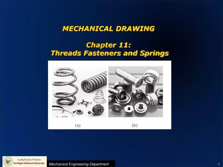
MECHANICAL DRAWING Chapter 11: Threads Fasteners and Springs. Objectives of threads and fasteners. 1. To hold parts together (Assembly). 3. To transmit power . 2. To provide for adjustment between parts (Drum). Chapter Objectives. Define and label the parts of a screw thread

E N D
Objectives of threads and fasteners 1. To hold parts together (Assembly). • 3. To transmit power 2. To provide for adjustment between parts (Drum).
Chapter Objectives • Define and label the parts of a screw thread • Identify various screw thread forms. • Draw detailed, schematic, and simplified threads. • Define typical thread specifications • Draw various screw head types. • Draw springs
Screw Thread Nomenclature • Screw thread: • External thread: a thread on the outside of a member (shaft). • Internal thread: a thread on the inside of a member (hole). • Major diameter: the largest diameter of the screw thread. • Minor diameter: the smallest diameter of the screw thread. • Pitch: the distance from a point on a screw thread to the corresponding point on the next thread measured parallel to the axis (US units = 1/ number of threads per inch). • Pitch diameter: the diameter of an imaginary cylinder passing through the threads where the widths of the threads and the width of the spaces are equal
Screw Thread Nomenclature • Lead: the distance that the screw advances in one turn. • Angle of a thread: the angle between the sides of the thread. • Crest: the outer surface of the thread • Root: the inner surface of the thread. • Side: • Axis of the screw: • From of the thread: the cross section of thread cut by a plane containing the axis • Series of thread: the standard number of threads per inch for various diameters.
Important notes: • Thread Form: • International standard form (SI metric). Most widely used. • United States forms (English units). USA, Great Britain and Canada. • Standardization of screw thread is very important
Screw Thread Forms • Sharp V thread: high friction because of full thread face. • American national: flatten roots and crests. General use. Replace by the following thread. • Unified thread (N): US standard thread (replaces the previous thread). Root is rounded, crest (rounded/flat). • Old standard US threads: (still included in the new standard - 11 series) • (UN or N); general. • (UNC or NC); course thread series. • (UNF or NF); fine thread series. • (UNS or NS); special series. • ●) Unified extra fine series (UNEF) Different number of threads per inch for various standard diameters
Screw Thread Forms • Metric thread (M): Standard (international screw thread fasteners ISO). Normally flat crest and root, could be rounded in external thread. Similar to the unified thread (lower depth). • Course thread (general purpose) • Fine thread • Square thread; power transmission (difficult to fabricate, and other problems). ACME thread is more used. • ACME thread: largely replaces the square thread. • ●) Worm standard thread; similar to the ACME thread but deeper.
Screw Thread Forms • Whitworth thread: replaced by the unified thread (angle=55) • Knuckle thread: usually rolled from sheet metal. (Ex. Electrical bulbs and sockets, bottle tops, …etc). • Buttress thread: transmits power in one direction only. High strength requirements. • ASME standards == American Society of • Mechanical Engineers.
Thread Pitch, Right and Left-Hand Threads & Single and Multiple Threads • Thread Pitch: • Right and Left-Hand Threads • Single and Multiple Threads
Drawing a Thread • Simplified and Schematic Internal Thread symbols
Detailed representation: External Metric, Unified, & American National Threads (DRAWING)
Thread Fits • American National Thread Fits • A ≡ external thread • B ≡ internal thread • Class 1 fit: Clearance between mating parts is essential for rapid assembly, (1A, 1B). • Class 2 fit: High quality of commercial thread product, (2A, 2B). • Class 3 fit: Very high quality of commercial thread product (high cost), (3A, 3B) • Metric and Unified Thread Fits • g ≡ external thread • H ≡ internal thread • General-purpose application: (6H for internal, 6g for external) ≡ (2A, 2B). • Closer fit: (6H for internal, 5g6g for external)
Detailed representation: Internal Metric, Unified, & American National Threads (DRAWING) • Note that slope line is in the opposite direction of the external thread as you see internal threads!
Detailed representation: Internal Metric, Unified, & American National Threads (DRAWING) • Note that slope line is in the opposite direction of the external thread as you see internal threads!
Detailed External Square Thread Use the same table for square and acme threads
Detailed Internal Square Thread Lines from crest to crest Lines from root to screw axis
Phantom Lines and Threads in Assembly • Phantom Lines • For long threads use • phantom (hidden) lines • Threads in Assembly • Stud, bolt heads, and • nuts are not sectioned • External and internal • threads are shown in • V-shapes
Bolts, Studs, and Screws Threaded at both ends Greater thread length One of the parts is threaded (no nut)
Standard Bolts and Nuts • Inch and metric sizes • chamfered at 15-30o • Regular Heads & Bolts • (W = 1½D, H = ⅔D, T =⅞ D) • Heavy Heads & bolts • (structure) • (W = 1½D + ⅛" (3mm) • H = ⅔D, T = D) • See Table in Appendix 20for standard bolts and nuts dimensions (no standard for bolt lengths) • Inch sizes only • Chamfered at 30o • (W = 1½D, H = ⅔D, T =⅞ D) Thread Length: Screws up to 6" length = 2D+¼" (6mm) Screws over 6" length = 2D+½" (12mm)
Standard Bolts and Nuts Across Corners Across Flats
Standard Cap Screws All screws except (e) can be drawn directly as in figures. For exact dimensions see table (A21)
Standard Machine Screws (Smaller, Thread all the length) All screws can be drawn directly as in figures. For exact dimensions see table (A21)
Keys, Pins, and Rivets (Keys) Square or Flat Keys Gib Head Key Woodruff Keys and Key Slot Cutter Pratt & Whitney Key
Keys, Pins, and Rivets (Keys Drawing) Square and Flat Keys
Keys, Pins, and Rivets (Keys Drawing) Gib Head Keys
Keys, Pins, and Rivets (Keys Drawing) Pratt and Whitney Keys
Keys, Pins, and Rivets (Keys Drawing) Woodruff keys
Keys, Pins, and Rivets (Keys Drawing) Woodruff key solt
Keys, Pins, and Rivets (Machine Pins) • Taper Pin: • Used to fasten collars to shaft Collars See table A31 for standard diameters for given lengths
Keys, Pins, and Rivets (Rivets) • Usage: • Permanent fastening used to hold sheet metal or rolled steel together. • Made of wrought iron, carbon steel, copper, or other metals. • Hole diameter is slightly larger than the diameter of the rivet. • Rivet diameter d = 1.2 to 1.4 t: thickness of the sheet • A riveting machine is used to drive the rivet and forms the head on the plain end. This causes the rivet to swell and fill the hole tightly.
Keys, Pins, and Rivets (Rivets) • Riveted Joints :
Springs (Representation/Drawing) • Schematic:
Springs (Representation/Drawing) • Detailed: