Download
1 / 24
280 likes | 514 Views
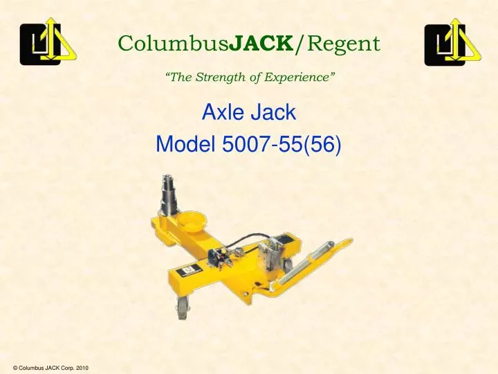
Columbus JACK /Regent “The Strength of Experience”. Axle Jack Model 5007-55(56). Capacity 50 tons Hydraulic Stroke 12 inches Screw Extension 3.5 inches Closed Height 7 inches Extended Height 22.5 inches Operating Pressure First Stage 4020 psi

E N D
ColumbusJACK/Regent “The Strength of Experience” Axle Jack Model 5007-55(56)
Capacity 50 tons Hydraulic Stroke 12 inches Screw Extension 3.5 inches Closed Height 7 inches Extended Height22.5 inches Operating Pressure First Stage 4020 psi Second Stage 5950 psi Third Stage 9690 psi 5007-55(56)
Maximum Towing Speed 3 mph 5007-55(56)
Cylinder Assy Hand Pump Air Pump 5007-55
Snap Ring Cylinder Bushing 1st Stage Ram 2nd Stage Ram 3rd Stage Ram O-Ring & Backup Ring 5007-55
Check hydraulic fluid in reservoir. If low, fill with mineral based fluid compatible with Buna-N seal material. For operation at temperatures below 32oF (0oC), replace 25% of the hydraulic fluid with kerosene. Check for missing parts, damage or leakage on hand pump assembly. Check pump piston OD for scoring and rust pits. Replace as necessary. If piston is leaking, fluid replace o-ring and backup ring. Inspection
Replace missing parts as required. Inspection • Check cup adapter condition. • Replace if damaged or missing. • Insure adapter is securely attached to screw extension. • Check screw extension. • Replace if damaged. • Insure screw extension stop is in place to prevent its removal. • Insure the screw extension will thread up and down freely.
Inspection • Check top of cylinder assembly for leakage. • If fluid exists, cycle ram full stroke and clean all excess fluid from ram, then lower ram completely. Fully extend ram. If fluid continues to be present, disassembly cylinder and replace all seals. • Check casters and floating wheel for damage or excessive tread wear. • Replace if damaged. • Insure all hardware is tightened securely.
Inspection • Check attaching hardware for cylinder assembly to frame. • Insure all hardware is tightened securely. • If applicable, adjust leveling screw to insure cylinder base is level to ground. • Check base of cylinder for proper thickness. • Verify cylinder snap rings are fully engaged in grooves. • Tap snap ring into groove with a hammer. Replace if snap ring will not stay in groove.
Inspection • Verify rain hat is operational. • Check hydraulic lines and fittings for damage and leakage. • Replace if damaged. • Check reservoir fill plug and verify vent is open. • Drain air filter. • Insure air relief valve/regulator is undamaged. • Check pressure setting of regulator.
Locate jack under aircraft lifting point. Unscrew the screw extension as required. Operate pump until rams have raised aircraft to desired height. Operation – To Raise
Slowly open release valve to lower rams. Lower screw extension completely. Place rain hat over cylinder. Operation – To Lower
Control Valve Vacuum Pump Evac-U-Tract (-56) • Evac-U-Tract provides air assist in the retraction of the rams by creation a suction across the reservoir that “pulls” the oil from the cylinder.
Operate jack same as without Evac-U-Trac. Operation – To Raise
Slowly open jack release valve and allow rams to retract until aircraft tires are completely on the ground. Operate Evac-U-Trac to lower rams completely. Lower screw extension completely. Place rain hat over cylinder. Operation – To Lower
Relief valve should be checked at least annually to insure it is operating properly. Cylinder assembly should be pressure checked at rated pressure after seal changes. Cylinder must be tested with first and second stage fully extended and the third stage partially extended. Testing Procedure
Relief valve should be set between rated capacity and 110% rated capacity. Close release valve and pressurize jack against tester using hand pump. Pump handle will go “soft” when relief valve setting is reached. If adjustment is required: • Remove spring pin. Relief Valve Adjustment • Open release valve to release pressure in jack
Intake Check Valve Relief Valve Poppet Relief Valve Spring Relief Valve Adjustment Screw Release Valve Inlet Oil Screen Pressure Check Valve Relief Valve Adjustment
To increase relief pressure, release pressure and rotate adjusting screw clockwise. Relief Valve Adjustment • Close release valve and pressurize jack against tester using hand pump. • To decrease relief pressure, release pressure and rotate adjusting screw counterclockwise. • Verify relief valve is set in the correct range and re-adjust as required.
Re-install spring pin. Relief Valve Adjustment • Open release valve and lower ram(s) completely.