Download
1 / 24
320 likes | 615 Views
Chladni Patterns. From http://www.physics.brown.edu/Studies/Demo/waves/demo/3d4030.htm. Resonance Frequencies with the Pasco Chladni 174, 197, 254, 345, 396, 400, 490, 795, 950, 1060, 1400, 1725, 1900, 2105, 2260, and 2700. Chladni Plates. For Holographic Chladni see:

E N D
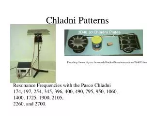
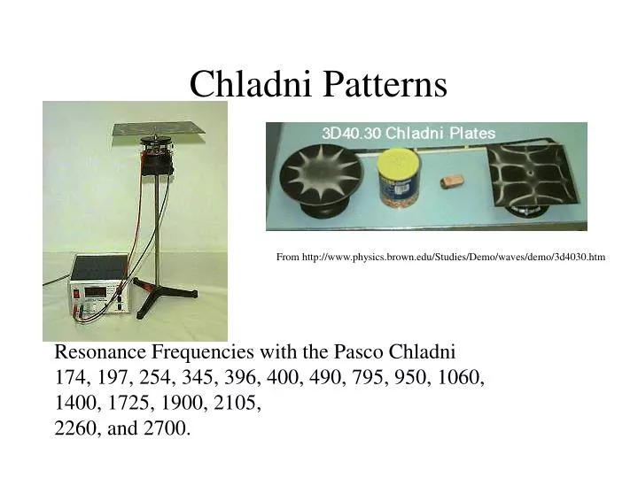
Chladni Patterns From http://www.physics.brown.edu/Studies/Demo/waves/demo/3d4030.htm Resonance Frequencies with the Pasco Chladni 174, 197, 254, 345, 396, 400, 490, 795, 950, 1060, 1400, 1725, 1900, 2105, 2260, and 2700.
Chladni Plates For Holographic Chladni see: http://www.stetson.edu/departments/physics/vholography/theory.htm Modal Analysis of Percussion Instruments Using Vibrational Holography Stetson University Department of Physics Research: Robert Bedford Faculty Mentor: Dr. Kevin Riggs http://www.alphaomega.se/english/chladnifig.html Chladni figures. What we are seeing in this illustration is primarily two things: areas that are and are not vibrating. When a flat plate of an elastic material is vibrated, the plate oscillates not only as a whole but also as parts. The boundaries between these vibrating parts, which are specific for every particular case, are called node lines and do not vibrate. The other parts are oscillating constantly. If sand is then put on this vibrating plate, the sand (black in the illustration) collects on the non-vibrating node lines. The oscillating parts or areas thus become empty. According to Jenny, the converse is true for liquids; that is to say, water lies on the vibrating parts and not on the node lines.
See http://www.ericjhellergallery.com/art/chladni.shtml The diagrams of Ernst Chladni (1756-1827) are the scientific, artistic, and even the sociological birthplace of the modern field of wave physics and quantum chaos. Educated in Law at the University of Leipzig, and an amateur musician, Chladni soon followed his love of science and wrote one of the first treatises on acoustics, "Discovery of the Theory of Pitch". Chladni had an inspired idea: to make waves in a solid material visible. This he did by getting metal plates to vibrate, stroking them with a violin bow. Sand or a similar substance spread on the surface of the plate naturally settles to the places where the metal vibrates the least, making such places visible. These places are the so-called nodes, which are wavy lines on the surface. The plates vibrate at pure, audible pitches, and each pitch has a unique nodal pattern. Chladni took the trouble to carefully diagram the patterns, which helped to popularize his work. Then he hit the lecture circuit, fascinating audiences in Europe with live demonstrations. This culminated with a command performance for Napoleon, who was so impressed that he offered a prize to anyone who could explain the patterns. More than that, according to Chladni himself, Napoleon remarked that irregularly shaped plate would be much harder to understand! While this was surely also known to Chladni, it is remarkable that Napoleon had this insight. Chladni received a sum of 6000 francs from Napoleon, who also offered 3000 francs to anyone who could explain the patterns. The mathematician Sophie Germain took he prize in 1816, although her solutions were not completed until the work of Kirchoff thirty years later. Even so, the patterns for irregular shapes remained (and to some extent remains) unexplained. Government funding of waves research goes back a long way! (Chladni was also the first to maintain that meteorites were extraterrestrial; before that, the popular theory was that they were of volcanic origin.) One of his diagrams is the basis for image, which is a playfully colored version of Chaldni's original line drawing. Chladni's original work on waves confined to a region was followed by equally remarkable progress a few years later. Check out http://www.kwantlen.bc.ca/~sci/phys/chladni.htm "Chladni Plates: How Big can They Be?", found in The Physics Teacher, Vol. 34, Nov. 1996, pp.508-509.
See http://www.phy.davidson.edu/jimn/Java/modes.html Chladni Figures and Vibrating Plates We find experimentally and theoretically that thin plates or membranes resonate at certain "modes." This means due to initial conditions imposed upon the plate (i.e. fixed edges) the plate can vibrate only at certain allowable frequencies and will demonstrate predictable "node" patterns. Nodes are points on the plate that vibrate with zero amplitude, while other surrounding points have non-zero amplitude. This concept can be seen with a vibrating string: tie one end of a string to a fixed object and smoothly vibrate the other end of the string. If vibrated fast enough, there will be a point or points in the middle that seem to be still while the rest of the string vibrates wildly. These points are the nodes. On a two dimmensional vibrating plate, the nodes are not points, but curves. With the circular plate, we most commonly observe concentric circular nodes and diametric modes, while with the rectangular plate, we commonly observe nodes parallel with the boundaries. To see some labortory work and a more technical discussion of node patterns click here. This applet demonstrates the mode patterns of vibrating circular and rectangular plates, usually called "Chaladni Plates" in honor of 18th century scientist Ernest Chladni. Chladni conducted extensive work on fixed circular plates and developed Chladni's Law which states that modal frequencies of fixed circular plates varies according to f~(m+2n)^2, where n is the number of circular nodes and m is the number of diametric nodes. The above applet allows the user to change values of "m" and "n" in both the fixed circular and fixed rectangular plates. Colors represent relative amplitudes of the waves, bright red being the highest. At the right, the frequency box displays a relative modal frequency value. If you right mouse-click on the plot, a copy of the canvas will appear, allowing you to compare several modes.
Simulated Results: frequency unknown n=4 m=0 Actual Results: frequency 112 n=4 m=0
Simulated Results: frequency unknown n=5 m=0 Actual Results: frequency 2700 n=5 m=0
Simulated Results: frequency unknown n=6 m=0 Actual Results: frequency 4000 n=6 m=0
Simulated Results: frequency unknown n=0 m=7 Actual Results: frequency 5750hz n=0 m=7
Actual Results: frequency 270hz n=4 m=0 Simulated Results: frequency unknown n=4 m=0 Predicted Results: frequency 255 n=4 m=0
Simulated Results: frequency unknown n=2 m=2 Actual Results: frequency 450hz n=2 m=2 Predicted Results: frequency unknown n=2 m=2
Weird Stuff • The next images show dramatic changes of the design on the plate with a little change of the frequency and at times at the same frequency.
Actual Results: frequency 155 Actual Results: frequency 150 You can see a switch of the pattern with only 5hz difference. If you start with the 150 and move to 155 you can get this change, but you cannot go from 155 to 150.
Actual Results: frequency 70 Actual Results: frequency 70 Here you can see a completely different design at the same frequency. If you start off with a low amplitude and slowly turn it up, at some where around 40-60 you get the new design. The reason for this we believe has to do with the amount of sand on the surface.
Some Thoughts • We found that the amount of sand on the plate could and would change the out come of the design on the plate. • To get some of the predicted designs we had to start from a base node and move up or down to the predicted node. • We also found that sometimes we would have to start out at a low amplitude and slowly increase it.
Things to make it better • If the plate was more stable it would hold the sand in a more uniform way and may not then effect the outcome. • I think a better signal generator would also help in the outcome.
Square Plate Mainly just pictures we did not pay to much attention to this one because of the experiments with the circle plate