Download
1 / 112
1.19k likes | 1.56k Views
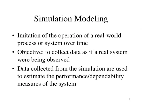
GEZEL Modeling and Simulation. Patrick Schaumont Virginia Tech Dept. of Electrical and Computer Engineering September 2010. Outline. RTL Architecture vs Modeling Datapath Cycle-based modeling Expressions in hardware Modules Finite State Machines FSMD Tools Simulation

E N D
GEZEL Modeling and Simulation Patrick Schaumont Virginia Tech Dept. of Electrical and Computer Engineering September 2010
Outline • RTL Architecture vs Modeling • Datapath • Cycle-based modeling • Expressions in hardware • Modules • Finite State Machines • FSMD • Tools • Simulation • Value Change Dump • Hierarchy • Semantics • Proper FSMD • Transformations • Library Modules • Examples
RTL • RTL = Register Transfer Level • An abstraction level above logic gates that abstracts time in clock cycles R2 R1 Logic Function 1 Register Transfer R1= LogicFunction(R2)
RTL • The Logic Function can be anything that can be computed in a single clock cycle R2 R1 Logic Function One Clock Cycle
RTL • Bit-parallel description: R2 and R1 can be wider than a single bit R2 R1 Logic Function = = One Clock Cycle
RTL • For example, Logic Function = inversion • R1 = ~R2 • Number of inverters = Wordlength of R2 • WL R1 = WL R2 R2 R1 n
RTL • Or, for example, Logic Function = squaring • R1 = R22 • WL R1 = 2x WL R2 R2 R1 n 2n mult n
RTL • RTL is Technology Independent • How much work you can do in a clock cycle • depends on the target technology used to implement the Logic Function • depends on the clock frequency selected for the design R2 R1 Logic Function
RTL • Therefore, the RTL designer needs to make sure that the Logic Function will be able to complete within a single clock cycle R2 R1 one clock cycle n short delay short delay long delay R2 R1 n 2n timingviolation mult n long delay
RTL • So RTL is a ... • bit-parallel, • technology-independent, • (and, in this course) synchronous, single-clock way to model hardware implementations
Simulation Cycle • The simulation cycle of RTL goes through two phases: • Evaluate (Logic Function) • Update (Registers) R2 R1 Logic Function
Simulation Cycle • The simulation cycle of RTL goes through two phases: • Evaluate (Logic Function) • Update (Registers) R2 R1 Logic Function Evaluate: Read output of R2, Calculate Logic, Determine input of R1 Update: For all registers, copy the input value to the output value
Simulation Cycle • The simulation cycle of RTL goes through two phases: • Evaluate (Logic Function) • Update (Registers) one clock cycle R2 R1 Logic Function Evaluate Update
Simulation Cycle • All evaluate phases are evaluated simultaneously (like real hardware) • Input R2 = LogFun1(Output R3) and Input R1 = LogFun2(Output R2) R3 R2 R1 Logic Function1 Logic Function2
Equivalent Finite State Machine R3 R3 you can think of this as Logic Function1 R2 R2 R1 R1 Logic Function2 Next ClockCycle Current ClockCycle (not a physical wire)
Equivalent Finite State Machine R R Logic Function • Arbitrary networks of logic and registers can always be reduced to single, equivalent finite state machine Next ClockCycle Current ClockCycle implemented as: R Logic Function
Simulation • Cycle-based Simulation has two phases ... • Evaluate: to calculate the outputs of the logic gates • Update:to determine the outputs of registers one clock cycle Just after the edge,you know only the outputs of the registers Just before the edge,you have determinedthe inputs of the registers
RTL Modeling • There are many languages available for RTL Modeling: VHDL, Verilog are mainstream. Others are SystemC, BlueSpec, MyHDL, .. • We use GEZEL • http://rijndael.ece.vt.edu/gezel • Anything you write in GEZEL, you can also write in VHDL, Verilog, SystemC • GEZEL can also be translated (automatically) into VHDL
Outline • RTL Architecture vs Modeling • Datapath • Cycle-based modeling • Expressions in hardware • Modules • Finite State Machines • FSMD • Tools • Simulation • Value Change Dump • Hierarchy • Semantics • Proper FSMD • Transformations • Library Modules • Examples
RTL Modeling • Registers • Wires • Circuits • reg variables • sig variables • Expressions 1
Expressions in Hardware • 3-bit counter • reg is a register variable • ns(3) means unsigned, 3-bit • Note that the clock signal is implicit R1 reg r1 : ns(3); always { r1 = r1 + 1; } add 1
Expressions in Hardware Cycle Output r1 Input r1 0 0 1 1 reg r1 : ns(3); always { r1 = r1 + 1; } 2 3 4 5 6 7 8 9 Registers are assumed to be 0 in cycle 0(Like the clock signal, the reset signal is implicit)
Expressions in Hardware Cycle Output r1 Input r1 0 0 1 1 1 2 reg r1 : ns(3); always { r1 = r1 + 1; } 2 2 3 3 3 4 4 4 5 5 5 6 6 6 7 7 8 9 What happens in cycle 7?
Expressions in Hardware Cycle Output r1 Input r1 0 0 1 1 1 2 reg r1 : ns(3); always { r1 = r1 + 1; } 2 2 3 3 3 4 4 4 5 5 5 6 6 6 7 7 7 0 8 0 1 9 1 2 Overflow to zero!
Wire Variables reg r : ns(3); sig v : ns(3); always { v = r + 1; r = v << 1; } R • sig is a wire variable • Wires have no memory; they are aliases for expressions V add 1 << 1
Wire Variables reg r : ns(3); sig v : ns(3); always { v = r + 1; r = v << 1; } Cycle Output r Input r 0 0 1 2 3
Wire Variables reg r : ns(3); sig v : ns(3); always { v = r + 1; r = v << 1; } Cycle Output r Input r 0 0 2 1 2 2 3
Wire Variables reg r : ns(3); sig v : ns(3); always { v = r + 1; r = v << 1; } Cycle Output r Input r 0 0 2 1 2 6 2 6 3 6
Wire Variables reg r : ns(3); sig v : ns(3); always { v = r + 1; r = v << 1; } Cycle Output r Input r 0 0 2 1 2 6 2 6 6 3 6 6 (1 1 0) + 1 = (1 1 1) (1 1 1) << 1 = (1 1 1 0) (1 1 1 0) on ns(3) = (1 1 0)
Lexical Order • Lexical order of expressions is irrelevant • Assignment on sig can be substituted on the expression reg r : ns(3); sig v : ns(3); always { v = r + 1; r = v << 1; } reg r : ns(3); sig v : ns(3); always { r = v << 1; v = r + 1; } =
Lexical Order How does this circuit look like? • Lexical order of expressions is irrelevant • Assignment on reg are all parallel reg r : ns(3); reg v : ns(3); always { v = r + 1; r = v << 1; } reg r : ns(3); reg v : ns(3); always { r = v << 1; v = r + 1; } =
Lexical Order V R << 1 + 1 • Lexical order of expressions is irrelevant • Assignment on reg are all parallel reg r : ns(3); reg v : ns(3); always { v = r + 1; r = v << 1; } reg r : ns(3); reg v : ns(3); always { r = v << 1; v = r + 1; } =
Lexical Order • The detailed steps taken by the simulator are as follows: reg r : ns(3); sig v : ns(3); always { r = v << 1; v = r + 1; } • At the start of a clock cycle, only r (reg) is known • We cannot evaluate v<<1 until we know v • Therefore, the simulator will first evaluate v = r + 1 • Next, the simulator can evaluate the new value for r
Another Example reg r : tc(3); sig v1, v2 : tc(3); always { v2 = -r; v1 = (r < 0) ? v2 : r; r = (v1 << 1) | 1; } • tc(3) is a two's complement 3-bit value • | is a bitwise-or • What is the structural equivalent of this design?
Another Example reg r : tc(3); sig v1, v2 : tc(3); always { v2 = -r; v1 = (r < 0) ? v2 : r; r = (v1 << 1) | 1; } R • tc(3) is a two's complement 3-bit value • | is a bitwise-or <0 v2 unary- v1 (<<1)| 1
Expressions in Hardware reg r : tc(3); sig v1, v2 : tc(3); always { v2 = -r; v1 = (r < 0) ? v2 : r; r = (v1 << 1) | 1; } Cycle Read R V1 Write R • tc(3) is a two's complement 3-bit value • | is a bitwise-or • What is the behavior of this design? 0 0 1 2 3 4
Expressions in Hardware reg r : tc(3); sig v1, v2 : tc(3); always { v2 = -r; v1 = (r < 0) ? v2 : r; r = (v1 << 1) | 1; } Cycle Read R V1 Write R • tc(3) is a two's complement 3-bit value • | is a bitwise-or 0 0 0 1 1 1 1 3 2 3 3 -1 3 -1 1 3 4 3 3 -1
Impossible Design? sig b : ns(3); always { b = b + 1; } • What is the meaning of this design? b add 1
Impossible Design? sig b : ns(3); always { b = b + 1; } • What is the meaning of this design? • We cannot know b without knowing b .. • This is construction is invalid in RTL • Simulator flags this as a design error ('combinational loop') b add 1
Impossible Design? sig a, b : ns(3); always { a = b + 1; b = a; } • Does this solve the issue ?
Impossible Design? sig a, b : ns(3); always { a = b + 1; b = a; } • Does this solve the issue ? • No ! • The dependencies through wire variables still show a loop b a add 1
GEZEL Operators • GEZEL operators = Most C operators that can be conveniently mapped to a hardware implementation • Bitwise: a|b, a&b, a^b, ~a • Selection: a ? b : c • Arithmetic: a+b, a-b, a*b, -a • Arithmetic: a<<n, a>>n • Comparison: a<b, a>b, a<=b, a>=b, a!=b, a==b • Tricky operators (not supported): • Division, Modulo, Power • Math functions
GEZEL Operators • Data types are signed (tc), unsigned (ns), arbitrary-wordlength • Bit & type manipulation operators • Bit-selection: a[2] a = 1 0 1 1 -> a[2] = 0 • Sub-vector: a[3:2] a = 1 0 1 1 -> a[3:2] = a[2:3] = 1 0 • Concatenation: a # b a = 1 0 0 b = 1 1 -> a # b = 1 0 0 1 1 • Cast: (type) a a = 0 1 0 -> (ns(2)) a = 1 0 (decimal: 2) a = 0 1 0 -> (tc(2)) a = 1 0 (decimal: -2)
GEZEL Operators • What does this implement ? reg shift, seed : ns(5); reg ld : ns(1); always { shift = ld ? seed : (shift << 1) | (shift[1] ^ shift[4]); }
GEZEL Operators • What does this implement ? reg shift, seed : ns(5); reg ld : ns(1); always { shift = ld ? seed : (shift << 1) | (shift[1] ^ shift[4]); } seed[0] seed[1] seed[2] seed[3] seed[4] ld ld ld ld ld 0 1 2 3 4
GEZEL Operators • What does this implement ? reg v : ns(6); sig j : ns(3); always { j = 3; v = (tc(1)) j; }
GEZEL Operators • What does this implement ? reg v : ns(6); sig j : ns(3); always { j = 3; v = (tc(1)) j; } v j j[0]
Lookup Tables • There are no array variables (or for-loops) • There are lookup tables for constant arrays reg adr : ns(3); sig value : ns(8); lookup T1 : ns(8) = {5, 1, 3, 2, 4, 3, 6, 7}; always { value = T1(adr); }
Modules • Expressions by themselves can be encapsulated in modules which have input and output ports • Modules promote design reuse, abstraction XOR Module A Q B
Modules dp accumulator(in i : ns(3); out o : ns(3)) { reg a : ns(3); always { a = a + i; o = a; } • Input- and Output ports accumulator a + o i