Download
1 / 43
440 likes | 625 Views
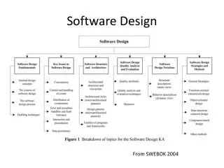
Software Design. Module and Modular Design Classes in Object-Oriented Modeling Structured Design and Structure Chart Component-Based Development (CBD) Web Services and SOA. Evolutions. Module Code only Class Data + Operations Web services Classes over the Internet.

E N D
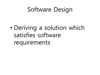
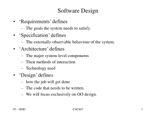
Software Design • Module and Modular Design • Classes in Object-Oriented Modeling • Structured Design and Structure Chart • Component-Based Development (CBD) • Web Services and SOA
Evolutions • Module Code only • Class Data + Operations • Web services Classes over the Internet
Module Module1 ' The argument x is passed by value ' The argument y is passed by reference Public Sub ABC(ByVal x As Integer, ByRef y As Integer) ' If ABC changes x, the changes do not affect a. ' If ABC changes y, the changes affect b. x = x + 1 y = y + 1 End Sub Public Sub Main() Dim a As Integer = 3 Dim b As Integer = 4 ABC(a, b) ' Call the procedure. Console.WriteLine("a = " & a) Console.WriteLine("b = " & b) ' You can force parameters to be passed by value, regardless of how ' they are declared, by enclosing the parameters in extra parentheses. ABC((x)) End Sub End Module
Dim a As Integer = 3 Dim b As Integer = 4 ABC(a, b) Console.WriteLine("a = " & a) Console.WriteLine("b = " & b) Before After a 3 3 b 4 5 Before After x 3 4 x y y Public Sub ABC(ByVal x As Integer, ByRef y As Integer) x = x + 1 y = y + 1 End Sub
Module and Modularity • Modules provide a separation between interface and implementation. • A module interface expresses the parameters that are provided and required (e.g., outputs and inputs) by the module. • Only the parameters defined in the interface are visible to other modules, not its internal implementation. • Information hiding Object-oriented programming
Definition: A class is a blueprint or prototype that defines the variables and the methods common to all objects of a certain kind.
Classes inherit state and behavior from their superclass. Inheritance provides a powerful and natural mechanism for organizing and structuring software programs.
Bicycle YourBicycle = New Bicycle() Biker You = New Biker() … YourBicyle.ChangeOwner(You) YourBicycle.ChangeGear(3) ….. Three components comprise a message: • the object to whom the message is addressed (bicycle) • the name of the method to perform (change gears) • any parameters needed by the method (to a higher gear)
Class Diagram: Attributes and Operations • Operation is a function that may be applied to objects in a class. • All objects in a class share the same operations. • A method is the implementation of an operation. • The same operation that may apply to different classes. • The method for the same operation in each class may be implemented differently. File - fileName - sizeInBytes - lastUpdate Person Geometric Objects - name : string - age : integer - job: string - address: string - color: Integer - position: Point + print + public visibility # protected visibility - private visibility + move ( delta : Vector) + select ( p : Point) : Boolean + rotate ( angle: Float ) + change_job + change_address
Operations and Methods • A message is sent from an object to a receiving object to invoke an operation. • The response of an operation depends on the class of the receiving object. • The details of a method are hidden from the user of the object. • Changing the method does not affect other classes. • Visibility: Minimize the visibility of a class by making only operations that are needed by a class public. Operations used by an object internally should be private. • Polymorphism: Takes on many forms. An operation may behave differently when applies on objects of different classes. • More than one class may have the same operation. However, the implementation of the operation may be different.
Modular Design • Functional partitioning into discrete scalable, reusable modules consisting of isolated, self-contained functional elements; • Rigorous use of well-defined modular interfaces, including object-oriented descriptions of module functionality; • Ease of change to achieve technology transparency and, to the extent possible, make use of industry standards for key interfaces.
Structure Chart Notations Module Calling Module Normal Procedure (Subroutine) Call Produce Paycheck Module Name Control Flag Library(Predefined) Module Retrieve Employee Record Data Data Module Name Called Module Offpage Global Data Store Sender System Device Receiver Global Data Store Used by Page-Jones Offpage Used by Page-Jones
Structure Chart Notations Sequence Decision Call A,1 A Call A,1 A IF Tx-Code = “A” Then Call A,2 Call A,2 ELSE IF Tx-Code = “B” Then Call A,3 Call A,3 ELSE IF Tx-Code =“C” THEN Call A,4 A,1 A,2 A,3 A,1 A,2 A,3 A,4 Iteration Lexical Inclusion Call A,1 Call A,1 Statement X Statement Y StatementZ Call A,3 A A Repeat Call A,2 Call A,3 Call A,4 Until EOF = “true” A,1 A,2 A,3 Statement X Statement T Statement Z A,1 A,2 A,3 A,4
Structure Chart Notations (Contd.) Notations used by Page-Jones Lexical Inclusion (The Hat Symbol) Decision Iteration
Structure Chart Notations Concurrent Activation Symbol Interface Table Asynchronous Activation of a Subtask Interface Table I/F# Input Output 1 2 1 A,B C 2 X Y,Z Physical Packaging Boundary Information Cluster Program X A B C D Modules A, B, and C has exclusive access to Data D
2.0 Enter Customer payments Answer to Problem 2 Remittance Remittance Customer-sold-to-name Customer-sold-to-name EOT Customer-ID Customer-payment Remittance 2.4 write Customer payment transaction 2.2 Add Customer information 2.5 Display Customer payment 2.1 Key remittance 2.3 Update A/R master Monthly-Statement-remittance Customer-ID Customer-record A/R-record New-A/R-record Invoice-remittance Customer-ID Old-A/R-record Customer-record Valid-account Customer-number Valid account Customer-ID Posting-ok No-record-on-file No-record-on-file 2.12 Key monthly statement remittance 2.11 Key invoice remittance 2.21 Get Customer record 2.22 Verify Customer account 2.31 Get receivable record 2.32 Verify Customer account 2.33 Rewrite A/R record Structure chart for program 2.0. Enter customer payment Exercise - 3
Type of Coupling Tightness of Coupling Goodness of Design Loose Good Normal Coupling Data Coupling Stamp Coupling Control Coupling Common Coupling Bad Tight Content Coupling
Normal Coupling A . Call B using X,Y . A . Call B. Y X B B Module A and module B are normally coupled if - A calls B - B returns to A All information passed between them are through parameter passing
UPDATE CUSTOMER MASTER FILE Valid Trans-action Updated Master Record Master Record Master Record Updated Master Record Valid Trans-action GET VALID INPUT PUT CUSTOMER MASTER UPDATE MASTER Transaction Transaction is valid Master Record Transaction VALIDATE CUSTOMER TRANSACTION GET INPUT Transaction Master Record Acct Number GET CUSTOMER TRANS GET CUSTOMER MASTER
Data Coupling Calculate Monthly payment of a House Loan Amount Mortgage Payment Term Interest Rate Calculate Mortgage Payment Module A and module B are data coupled if - A calls B - B returns to A - All information passed between them are through parameter passing - Each parameter is a data element
Stamp Coupling Calculate Monthly Payment of a House Mortgage Payment Customer Loan Record Calculate Mortgage Payment Two module A and B are data coupled if - A calls B - B returns to A - All information passed between them are through parameter passing - A composite piece of data is passed from one module to another
Control Coupling Produce paycheck Produce paycheck Tell the operator that “The Employee Record Is Not Found” Employee Record Not Found Employee ID Employee ID Employee Record Employee Record Retrieve Employee Record Retrieve Employee Record Control Flag Descriptive Flag
Scale of Cohesion Types of Cohesion Visibility Strength of Cohesion Maintainability FunctionalBlack box Strong Good SequentialNot-quite so Communicational black box Procedural Gray Temporal box LogicalTransparent Coincidentalor white box Weak Bad
Structure Chart and DFD This module is sequentially cohesive. This module is communicationally cohesive.
Simplify Communicational Cohesion Employee Name Employee Name Employee ID Employee YTD Total Deduction Employee ID Employee ID Employee YTD Total Deduction Get Employee Name Calculate YTD Total Deduction Get Employee Name Calculate YTD Total Deduction
Determine Module Cohesion Type of Cohesion Functional Does activities performed by the module related to a single problem-related task YES Sequential Is sequence important ? NO Communicational Data What relates the elements within the module ? Flow of control Procedural YES Is sequence important ? Temporal NO Neither data nor control Logical YES Are the activities performed by the elements in the same category? Coincidental NO
Customer Account Number Customer Loan Status Customer Name Customer Name DETERMINE CUSTOMER DETAILS A Communicationally Cohesive Module Halfway Up a Structure Chart Customer Account Number Customer Loan Status Customer Name DETERMINE CUSTOMER DETAILS Customer Account Number Customer Account Number Customer Name A Communicationally Cohesive Module at the Bottom of a Structure Chart FIND CUSTOMER NAME EVALUATE LOAN STATUS Each of These Functionally Cohesive Module is at the Bottom of a Structure
Satellite Trajectory A Functionally Cohesive Module Very High in a Structure Chart GET SATELLITE TRAJECTORY Ranges Azimuths Times Elevation GET ELEVATION GET TIMES GET AZIMUTHS GET RANGES
The Impact of Module Numbers on Cost High Total Cost Cost Intermodule Effects (Coupling) Cost Due to Intramodule Effects (Cohesion) Cost Due to Low Small Large Number of Modules
Four Basic Types of Modules Coordinate control Afferent (Input) Transform (Process) Efferent (Output)
Idea System Shape of a Structure Chart Afferent branch Transform branch Efferent branch
Idea System Shape of a Structure Chart High fan-out High fan-in
The Procedure of Deriving Structure Charts from Data Flow Diagrams Evaluate a detailed DFD Type of DFD Identify transaction types and transaction center of the DFD Identify central transform of the DFD Map to transform structure Map to transaction structure Refined the Structure Chart Transaction Analysis Transform Analysis
Transform Analysis Central Transform P P BOUNDARY A A BOUNDARY L OUTPUT INPUT B FUNCTION FUNCTION A A Afferent K P C Efferent E INPUT P FUNCTION D DATA STORE B OUTPUT B FUNCTION B P P J B F INPUT TRANSFORM FUNCTION FUNCTION D DATA STORE E C A H M D DATA STORE D P P P D OUTPUT G I INPUT TRANSFORM FUNCTION FUNCTION FUNCTION B C D
BOSS E J G F E, F, & G J & I I INPUT INPUT INPUT CENTRAL OUTPUT OUTPUT FUNCTION FUNCTION FUNCTION TRANSFORM FUNCTION FUNCTION B C D C B CONTROLLER C K E & F J I G & H INPUT TRANSFORM TRANSFORM OUTPUT FUNCTION FUNCTION FUNCTION FUNCTION A A B A
Transaction Analysis Structure Chart DFD Get Customer Transaction Process Customer Transaction Get Customer Transaction Get Customer Transaction Get Customer Transaction Tx-Code Get Customer Transaction Delete Customer Record Get Customer Transaction Change Customer Record Add New Customer A Transaction Selection Screen Customer Information System Main Menu 1. Add New Customer 2. Change Customer Record 3. Delete Customer Record
Determine Implementation Boundaries Real-time Manual On-line Batch
Processor Model: Allocation of essential Model Components to Processors Essential Model Processor 3 Processor 1 Allocating processes and data stores to processors Processor 2 Processor Level Implementation Model : Mainframe Netware LAN À À : : T1 À: UNIX Server TCP/IP