Download
1 / 45
450 likes | 688 Views
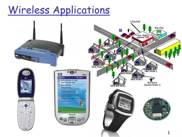
Wireless Applications. Why Wireless?. Flexible Low cost Easy to deploy Support mobility. Wireless Technologies. BW. UWB. WiMax. WiFi. 3G. Bluetooth. RFID. range. Basics of Wireless Communication. Signal Frequency allocation Signal propagation Antennas Multiplexing.

E N D
Why Wireless? • Flexible • Low cost • Easy to deploy • Support mobility
Wireless Technologies BW UWB WiMax WiFi 3G Bluetooth RFID range
Basics of Wireless Communication • Signal • Frequency allocation • Signal propagation • Antennas • Multiplexing
source decoding channel coding channel decoding source coding demodulation modulation Overview of Wireless Transmissions sender analog signal bit stream receiver bit stream
Signals I • Physical representation of data • Function of time and location • Classification • continuous time/discrete time • continuous values/discrete values • analog signal = continuous time and continuous values • digital signal = discrete time and discrete values
Signal II • Signal parameters of periodic signals: • period T, frequency f=1/T • amplitude A • phase shift • sine wave as special periodic signal for a carrier: s(t) = At sin(2 ft t + t) 1 0 t
Fourier Transform: Every Signal Can be Decomposed as a Collection of Harmonics 1 1 0 0 t t ideal periodicaldigital signal decomposition The more harmonics used, the smaller the approximation error.
Why Not Send Digital Signal in Wireless Communications? • Digital signals need • infinite frequencies for perfect transmission • however, we have limited frequencies in wireless communications
Frequencies for Communication twisted pair coax cable optical transmission 1 Mm 300 Hz 10 km 30 kHz 100 m 3 MHz 1 m 300 MHz 10 mm 30 GHz 100 m 3 THz 1 m 300 THz visible light VLF LF MF HF VHF UHF SHF EHF infrared UV VLF = Very Low Frequency UHF = Ultra High Frequency LF = Low Frequency SHF = Super High Frequency MF = Medium Frequency EHF = Extra High Frequency HF = High Frequency UV = Ultraviolet Light VHF = Very High Frequency Frequency & wave length: = c/f , wave length , speed of light c 3x10⁸m/s, frequency f
Frequencies and Regulations • ITU-R holds auctions for new frequencies, manages frequency bands worldwide (WRC, World Radio Conferences)
Why Need A Wide Spectrum: Shannon Channel Capacity • The maximum number of bits that can be transmitted per second by a physical channel is: W: frequency range that the media allows to pass through S/N: signal noise ratio
Signal, Noise, and Interference • Signal (S) • Noise (N) • Includes thermal noise and background radiation • Often modeled as additive white Gaussian noise • Interference (I) • Signals from other transmitting sources • SINR = S/(N+I) (sometimes also denoted as SNR)
dB and Power conversion • dB • Denote the difference between two power levels • (P2/P1)[dB] = 10 * log10 (P2/P1) • P2/P1 = 10^(A/10) • Example: P2 = 100 P1 • dBm and dBW • Denote the power level relative to 1 mW or 1 W • P[dBm] = 10*log10(P/1mW) • P[dB] = 10*log10(P/1W) • Example: P = 0.001 mW, P = 100 W
Outline • Signal • Frequency allocation • Signal propagation • Antennas • Multiplexing
Signal Propagation Ranges • Transmission range • communication possible • low error rate • Detection range • detection of the signal possible • no communication possible • Interference range • signal may not be detected • signal adds to the background noise sender transmission distance detection interference
Signal Propagation • Propagation in free space always like light (straight line) • Receiving power proportional to 1/d² (d = distance between sender and receiver) • Receiving power additionally influenced by • fading (frequency dependent) • shadowing • reflection at large obstacles • refraction depending on the density of a medium • scattering at small obstacles • diffraction at edges refraction shadowing reflection scattering diffraction
Multipath Propagation • Signal can take many different paths between sender and receiver due to reflection, scattering, diffraction • Time dispersion: signal is dispersed over time interference with “neighbor” symbols, Inter Symbol Interference (ISI) • The signal reaches a receiver directly and phase shifted distorted signal based on the phases of different parts LOS pulses multipath pulses LOS: Line Of Sight signal at sender signal at receiver
Fading • Channel characteristics change over time & location • e.g., movement of receiver and/or scatters • quick changes in the power received (short term/fast fading) • Additional changes in • distance to sender • obstacles further away • slow changes in the average power received (long term/slow fading) long term fading power t short term fading
Received Signal Power (dB) path loss shadow fading Rayleigh fading log (distance) Typical Picture
Antennas: Isotropic Radiator • Isotropic radiator: a single point • equal radiation in all directions (three dimensional) • only a theoretical reference antenna • Radiation pattern: measurement of radiation around an antenna z y z ideal isotropic radiator y x x Question: how does power level decrease as a function of d, the distance from the sender?
/4 /2 Antennas: Dipole • Real antennas are not isotropic radiators but, e.g., dipoles with lengths /4 on car roofs or /2 as Hertzian dipole shape of antenna proportional to wavelength
Outline • Signal • Frequency allocation • Signal propagation • Antennas • Multiplexing
Multiplexing • Multiplexing in 4 dimensions • space (si) • time (t) • frequency (f) • code (c) • Goal: multiple use of a shared medium • Important: guard spaces needed!
Space Multiplexing channels ki • Assign each region a channel • Pros • no dynamic coordination necessary • works also for analog signals • Cons • Inefficient resourceutilization k1 k2 k3 k4 k5 k6 c t c s1 t s2 f f c t s3 f
Frequency Multiplexing • Separation of the whole spectrum into smaller frequency bands • A channel gets a certain band of the spectrum for the whole time • Pros: • no dynamic coordination necessary • works also for analog signals • Cons: • waste of bandwidth if the traffic is distributed unevenly • Inflexible • guard spaces k1 k2 k3 k4 k5 k6 c f t
Time Multiplex • A channel gets the whole spectrum for a certain amount of time • Pros: • only one carrier in themedium at any time • throughput high even for many users • Cons: • precise synchronization necessary c f t
Time and Frequency Multiplexing • Combination of both methods • A channel gets a certain frequency band for a certain amount of time (e.g., GSM) • Pros: • better protection against tapping • protection against frequency selective interference • higher data rates compared tocode multiplex • Cons: • precise coordinationrequired k1 k2 k3 k4 k5 k6 c f t
Code Multiplexing • Each channel has a unique code • All channels use the same spectrum simultaneously • Pros: • bandwidth efficient • no coordination and synchronization necessary • good protection against interference and tapping • Cons: • lower user data rates • more complex signal regeneration • Implemented using spread spectrum technology c f t
Basics of Wireless Communication (more) • Signal • Frequency allocation • Signal propagation • Antennas • Multiplexing • Modulation • Spread spectrum
source decoding channel coding channel decoding source coding demodulation modulation Overview of Wireless Transmissions sender analog signal bit stream receiver bit stream
Modulation I • Digital modulation • digital data is translated into an analog signal (baseband) • Analog modulation • shifts center frequency of baseband signal up to the radio carrier • Reasons • Antenna size is on the order of signal’s wavelength • More bandwidth available at higher carrier frequency • Medium characteristics: path loss, shadowing, reflection, scattering, diffraction depend on signal’s wavelength
analog baseband signal digital data digital modulation analog modulation radio transmitter 101101001 radio carrier analog baseband signal digital data analog demodulation synchronization decision radio receiver 101101001 radio carrier Modulation and Demodulation
Modulation Schemes • Amplitude Modulation (AM) • Frequency Modulation (FM) • Phase Modulation (PM)
Digital Modulation • Modulation of digital signals known as Shift Keying • Amplitude Shift Keying (ASK): • Pros: simple • Cons: susceptible to noise • Example: optical system, IFR 1 0 1 t
Digital Modulation II • Frequency Shift Keying (FSK): • Pros: less susceptible to noise • Cons: requires larger bandwidth 1 0 1 t 1 0 1
Digital Modulation III • Phase Shift Keying (PSK): • Pros: • Less susceptible to noise • Bandwidth efficient • Cons: • Require synchronization in frequency and phase complicates receivers and transmitter t
Q I 1 0 Q 11 10 I • QPSK (Quadrature Phase Shift Keying): • 2 bits coded as one symbol • needs less bandwidth compared to BPSK • symbol determines shift of sine wave • Often also transmission of relative, not absolute phase shift: DQPSK - Differential QPSK 00 01 A t 01 11 10 00 Phase Shift Keying • BPSK (Binary Phase Shift Keying): • bit value 0: sine wave • bit value 1: inverted sine wave • very simple PSK • low spectral efficiency • robust, used in satellite systems
Example: 16-QAM (4 bits = 1 symbol) Symbols 0011 and 0001 have the same phase φ,but different amplitude a. 0000 and 1000 have same amplitude but different phase Used in Modem Q 0010 0001 0011 0000 φ I a 1000 Quadrature Amplitude Modulation • Quadrature Amplitude Modulation (QAM): combines amplitude and phase modulation • It is possible to code n bits using one symbol • 2n discrete levels • bit error rate increases with n
Outline • Signal • Frequency allocation • Signal propagation • Antennas • Multiplexing • Spread spectrum
Spread spectrum technology • Problem of radio transmission: frequency dependent fading can wipe out narrow band signals for duration of the interference • Solution: spread the narrow band signal into a broad band signal using a special code • Side effects: • coexistence of several signals without dynamic coordination • tap-proof • Alternatives: Direct Sequence, Frequency Hopping signal power interference spread signal power spread interference detection at receiver f f
Effects of Spreading and Interference dP/df dP/df user signal broadband interference narrowband interference i) ii) f f sender dP/df dP/df dP/df iii) iv) v) f f f receiver
channelquality 2 2 2 2 2 1 frequency spreadspectrum Spreading and frequency selective fading channelquality narrowband channels 2 1 5 6 3 4 frequency narrow bandsignal guard space spread spectrum channels