Download
1 / 30
350 likes | 1.53k Views
ASHRAE Std 62 update An Outline. General commentsVentilation Rate ProcedureIndoor Air Quality ProcedureQuestions. . . ASHRAE Standard 62.1-2007

E N D
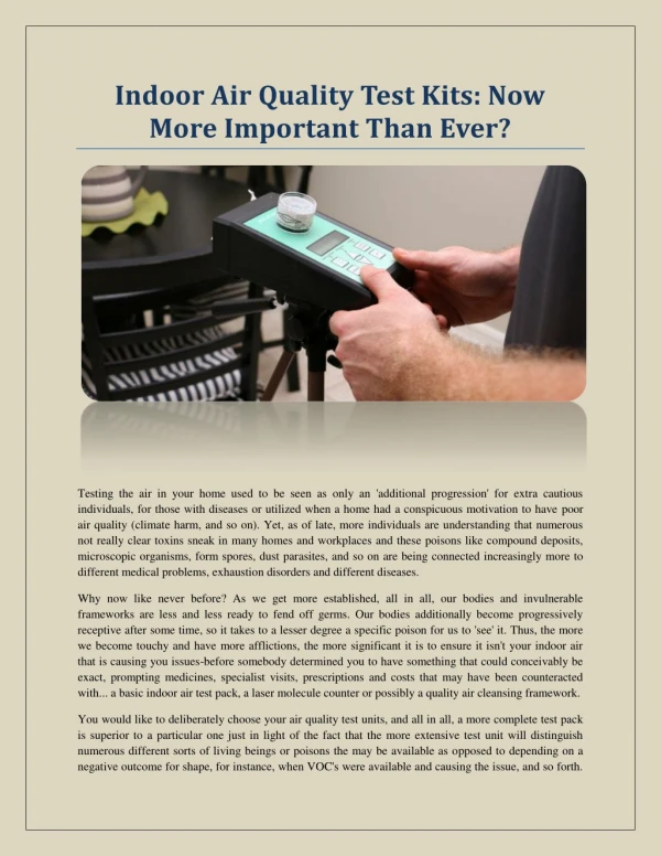
1. ASHRAE 62.1-2007 Ventilation for Acceptable Indoor Air Quality ASHRAE 62.1 update:Ventilation Rate Procedure & IAQ Procedure This presentation is the companion to a presentation titled ASHRAE 62.1 Update � Overview, Where Are We Now?
The companion presentation explains the requirements of ASHRAE Standard 62.1-2007 but does not explain the calculation requirements. Ideally, this presentation follows the overview presentation. Please be aware that there is more to complying with standard 62.1 than just the calculation of ventilation rates. Acceptable Indoor air quality requires more than ventilation. This presentation is the companion to a presentation titled ASHRAE 62.1 Update � Overview, Where Are We Now?
The companion presentation explains the requirements of ASHRAE Standard 62.1-2007 but does not explain the calculation requirements. Ideally, this presentation follows the overview presentation. Please be aware that there is more to complying with standard 62.1 than just the calculation of ventilation rates. Acceptable Indoor air quality requires more than ventilation.
2. ASHRAE Std 62 updateAn Outline Today�s presentation is going to focus on the history and recent updates of Standard 62.1,Ventilation for Acceptable Indoor Air Quality. We�ll discuss the key ventilation-related changes that have occurred and their impact on ventilation system design. We will also explain the continuous maintenance process that this standard operates under, and the processes by which the user can request standard interpretations and submit change proposals. Today�s presentation is going to focus on the history and recent updates of Standard 62.1,Ventilation for Acceptable Indoor Air Quality. We�ll discuss the key ventilation-related changes that have occurred and their impact on ventilation system design. We will also explain the continuous maintenance process that this standard operates under, and the processes by which the user can request standard interpretations and submit change proposals.
3. ASHRAE Standard 62.1-2007 & Related Activities� Std 62.1-2007 is the current version
IMC & UMC adopted equations and ventilation rates
Several educational courses are available from ASHRAE The current version of ASHRAE 62.1 is 2007. It is written in code adoptable language and is an ANSI consensus standard. The ventilation rate calculations and basic rates in the current International Mechanical Code and Uniform Mechanical Code are from ASHRAE 62.1. ASHRAE provides several educational courses. Course information is available on the ASHRAE website.The current version of ASHRAE 62.1 is 2007. It is written in code adoptable language and is an ANSI consensus standard. The ventilation rate calculations and basic rates in the current International Mechanical Code and Uniform Mechanical Code are from ASHRAE 62.1. ASHRAE provides several educational courses. Course information is available on the ASHRAE website.
4. Ventilation requirements 6.0 Procedures 6.1 General. Ventilation Rate Procedure or IAQ Procedure
6.1.1 Ventilation Rate Procedure. Prescribes rates & procedures based on typical space contaminant sources & source strengths
6.1.2 IAQ Procedure. Requires calculation of rates based on analysis of contaminant sources, concentration targets and perceived air quality targets This slide shows that there are two different procedures that can be used to design ventilation systems for a building in the case of mechanical ventilation systems. These are a) Ventilation Rate Procedure and b) IAQ procedure. VRP is a prescriptive procedure that specifies minimum outdoor airflow rates based on contaminant sources and strengths that are typical for the listed space. The rates are meant to dilute and exhaust odorous bioeffluents from occupants and odorous and sensory irritant contaminants from other sources typical of that space type. IAQ procedure is a performance-based design procedure in which calculations of outdoor airflow rates are based on analysis of contaminant sources, target concentrations and perceived air quality targets. The IAQ procedure allows designers to take credit for source-control and removal measures, such as low emission materials and gas-phase air cleaning devices.This slide shows that there are two different procedures that can be used to design ventilation systems for a building in the case of mechanical ventilation systems. These are a) Ventilation Rate Procedure and b) IAQ procedure. VRP is a prescriptive procedure that specifies minimum outdoor airflow rates based on contaminant sources and strengths that are typical for the listed space. The rates are meant to dilute and exhaust odorous bioeffluents from occupants and odorous and sensory irritant contaminants from other sources typical of that space type. IAQ procedure is a performance-based design procedure in which calculations of outdoor airflow rates are based on analysis of contaminant sources, target concentrations and perceived air quality targets. The IAQ procedure allows designers to take credit for source-control and removal measures, such as low emission materials and gas-phase air cleaning devices.
5. Ventilation Requirements 6.2 Ventilation Rate Procedure 6.2 Ventilation Rate Procedure
6.2.1 Outdoor Air Treatment. If outdoor air is judged to be unacceptable per Section 4.1 assessment
Use MERV 6 filter in PM10 non-attainment regions
Use 40% efficient ozone filter in some ozone non-attainment regions
Other � document assumptions 6.2.1 air treatment refers to the assessment of the national ambient-air quality standards for outdoor air addresses the course of action for outdoor air treatment if a building is located in an area where the outdoor air exceeds the national air quality standards.
Air cleaning devices are to be used if the PM10 standard is exceeded.
Air cleaning devices for ozone shall be provided when the second-highest daily maximum 1-hour average concentration exceeds 0.160 ppm. Very few locations in the US exceed this limit. For US locations, ozone air cleaning must operate when the 1-hour average ozone concentration is expected to exceed the 0.160 ppm (313 �g/m3) , that is, when the Air Quality Index forecast exceeds 151 (category red, purple or maroon). This forecast is available in local media or at the AIRNow Web site at www.epa.gov
For nonattainment for other than PM10 or severe 1 hour ozone, assumptions about air quality must be documented.6.2.1 air treatment refers to the assessment of the national ambient-air quality standards for outdoor air addresses the course of action for outdoor air treatment if a building is located in an area where the outdoor air exceeds the national air quality standards.
Air cleaning devices are to be used if the PM10 standard is exceeded.
Air cleaning devices for ozone shall be provided when the second-highest daily maximum 1-hour average concentration exceeds 0.160 ppm. Very few locations in the US exceed this limit. For US locations, ozone air cleaning must operate when the 1-hour average ozone concentration is expected to exceed the 0.160 ppm (313 �g/m3) , that is, when the Air Quality Index forecast exceeds 151 (category red, purple or maroon). This forecast is available in local media or at the AIRNow Web site at www.epa.gov
For nonattainment for other than PM10 or severe 1 hour ozone, assumptions about air quality must be documented.
6. Air Data: PM10 This map shows PM10 nonattainment areas as of December 2007. Be sure to refer to the latest data from EPA.
Speaker should check current compliance status.This map shows PM10 nonattainment areas as of December 2007. Be sure to refer to the latest data from EPA.
Speaker should check current compliance status.
7. Air Data: Ozone When one hour ozone concentrations exceed 160 ppb, ozone filtration is required
Speaker should check current compliance status..When one hour ozone concentrations exceed 160 ppb, ozone filtration is required
Speaker should check current compliance status..
8. Ventilation requirements 6.2 Ventilation Rate Procedure 6.2.2 Zone Calculations.
Use new Table 6.1 rates (both cfm/person and cfm/sf) to find breathing zone outdoor airflow: This shows the method for the calculation of the breathing zone outdoor airflow. In determining the breathing zone outdoor airflow, consideration is given to both the occupant related and the building (or material) related ventilation requirements. Rp is the rate per person. Pz is the maximum number of people expected to occupy the zone. Ra is the rate per unit area. Az is the area of the zone.This shows the method for the calculation of the breathing zone outdoor airflow. In determining the breathing zone outdoor airflow, consideration is given to both the occupant related and the building (or material) related ventilation requirements. Rp is the rate per person. Pz is the maximum number of people expected to occupy the zone. Ra is the rate per unit area. Az is the area of the zone.
9. Table 6-1 provides values of Rp and Ra for different occupancies. The table also provides default occupant densities that are to be used if accurate occupancy estimates are not available. The table also provides the air class for each occupancy.Table 6-1 provides values of Rp and Ra for different occupancies. The table also provides default occupant densities that are to be used if accurate occupancy estimates are not available. The table also provides the air class for each occupancy.
10. GENERAL NOTES FOR TABLE 6-1
1 Related requirements: The rates in this table are based on all other applicable requirements of this standard being met.
2 Smoking: This table applies to no-smoking areas�
4 Default occupant density: The default occupant density shall be used when actual occupant density is not known. These are three of the most important notes for Table 6-1�.These are three of the most important notes for Table 6-1�.
11. Ventilation Rate ProcedureMinimum Ventilation Rates Table 6-1: Minimum breathing-zone rates for 63 categories This is an example of the minimum ventilation rates specified in Table 6.1. It compares the values in Std 62.1 � 2007 with those in Std 62-2001.
Rationale for change
Rates based on research, experience and judgment.
Research on the occupant component : There have been a number of laboratory and field studies of the amount of ventilation air required to dilute occupant-generated odors and irritants. A consistent observation is that about 15 cfm (7.5 L/s) will satisfy a substantial majority (about 80%) of unadapted persons (visitors) in the space. Some studies showed that a significant adaptation occurs for bioeffluents but less to building materials. Data for adapted persons are limited but a 1983 study shows that about 5 cfm (2.5 L/s) will satisfy a substantial majority of adapted occupants.
Research on the building component : There have been several studies of source strengths associated with sensory pollutants from the building itself. The results indicate a wide range of building source strengths. When these source strengths are converted to ventilation requirements needed to satisfy about 80% of unadapted visitors to a space, the mean value is about 0.39 cfm/ft2 (2 L/s-m2) for offices and class rooms, 0.53 cfm/ft2 (2.7 L/s-m2) for kindergartens and 0.66 cfm/ft2 (3.3 L/s-m2) for assembly halls.
Research on overall rates in office buildings : Several field studies indicate that an outdoor air supply of 20 cfm (10 L/s) per person is very likely to be associated with lower rates of sick building syndrome symptoms (and consequently more acceptable perceived indoor air quality) in office spaces. These measured ventilation rates include the combined impacts of occupant and building sources as well as some degree of ventilation system efficiency.
Experience : Experience with successful existing buildings were considered, including buildings built under the 1981 Standard when outdoor air rates were a third or less of the rates required after 1989.However, this experience, which was largely anecdotal, must be weighed by the fact that actual ventilation rates in buildings are unlikely to be equal to the values required by the Standard at the time they were built. One study involving about 3000 individual ventilation rate measurements in more than a dozen office buildings found that about half the measured outdoor ventilation rates were below the design values. The European Audit Project study of 56 office buildings in 9 countries found that ventilation rates varied by a factor of two above or below the designed ventilation rates. Anecdotal experience provides a useful basis to limit proposed ventilation rates so that they are neither overly high nor low.
Judgment : Because of the limited breadth of available research (most focus only on offices, for example) and the imprecise nature of research results and anecdotal experience in existing buildings, ventilation rates were determined to a large extent based on the collective experience and judgment of the committee members who developed the Standard since the early 1990s. It should be noted that prior versions of the Standard were even more reliant on committee judgment since even less research as well as less experience with modern buildings was available at the time. This is an example of the minimum ventilation rates specified in Table 6.1. It compares the values in Std 62.1 � 2007 with those in Std 62-2001.
Rationale for change
Rates based on research, experience and judgment.
Research on the occupant component : There have been a number of laboratory and field studies of the amount of ventilation air required to dilute occupant-generated odors and irritants. A consistent observation is that about 15 cfm (7.5 L/s) will satisfy a substantial majority (about 80%) of unadapted persons (visitors) in the space. Some studies showed that a significant adaptation occurs for bioeffluents but less to building materials. Data for adapted persons are limited but a 1983 study shows that about 5 cfm (2.5 L/s) will satisfy a substantial majority of adapted occupants.
Research on the building component : There have been several studies of source strengths associated with sensory pollutants from the building itself. The results indicate a wide range of building source strengths. When these source strengths are converted to ventilation requirements needed to satisfy about 80% of unadapted visitors to a space, the mean value is about 0.39 cfm/ft2 (2 L/s-m2) for offices and class rooms, 0.53 cfm/ft2 (2.7 L/s-m2) for kindergartens and 0.66 cfm/ft2 (3.3 L/s-m2) for assembly halls.
Research on overall rates in office buildings : Several field studies indicate that an outdoor air supply of 20 cfm (10 L/s) per person is very likely to be associated with lower rates of sick building syndrome symptoms (and consequently more acceptable perceived indoor air quality) in office spaces. These measured ventilation rates include the combined impacts of occupant and building sources as well as some degree of ventilation system efficiency.
Experience : Experience with successful existing buildings were considered, including buildings built under the 1981 Standard when outdoor air rates were a third or less of the rates required after 1989.However, this experience, which was largely anecdotal, must be weighed by the fact that actual ventilation rates in buildings are unlikely to be equal to the values required by the Standard at the time they were built. One study involving about 3000 individual ventilation rate measurements in more than a dozen office buildings found that about half the measured outdoor ventilation rates were below the design values. The European Audit Project study of 56 office buildings in 9 countries found that ventilation rates varied by a factor of two above or below the designed ventilation rates. Anecdotal experience provides a useful basis to limit proposed ventilation rates so that they are neither overly high nor low.
Judgment : Because of the limited breadth of available research (most focus only on offices, for example) and the imprecise nature of research results and anecdotal experience in existing buildings, ventilation rates were determined to a large extent based on the collective experience and judgment of the committee members who developed the Standard since the early 1990s. It should be noted that prior versions of the Standard were even more reliant on committee judgment since even less research as well as less experience with modern buildings was available at the time.
12. Ventilation Rate ProcedureMinimum Ventilation Rates This slide shows the effect of the changes assuming default occupancy. The rates for 62.1-2007 calculated at default occupancy for 1000 sq ft can be compared to the rates per person in the previous standard.This slide shows the effect of the changes assuming default occupancy. The rates for 62.1-2007 calculated at default occupancy for 1000 sq ft can be compared to the rates per person in the previous standard.
13. Zone Outdoor Airflow Use new Table 6.2 defaults to find zone air distribution effectiveness, Ez
Find zone outdoor airflow for each zone: The ventilation air provided to the breathing zone must be adjusted to account for ventilation effectiveness. The value Voz is the quantity of outdoor air provided to the zone by the supply air distribution system.The ventilation air provided to the breathing zone must be adjusted to account for ventilation effectiveness. The value Voz is the quantity of outdoor air provided to the zone by the supply air distribution system.
14. Ventilation Requirements 6.2 Ventilation Rate Procedure 6.2.3 Single-Zone Systems. Find system-level outdoor air intake flow:
After finding minimum zone outdoor airflow values, the designer must determine outdoor air intake flow Vot, based on system type and the appropriate equations.
Single-zone systems : This equation is to be used for system-level outdoor air intake flow when one AHU supplies a mixture of outdoor air and recirculated air to only ONE zone.
100% outdoor air systems : This equation is to be used for determining the outdoor air intake flow when one AHU supplies only outdoor air to one or more zones.
Note that both single-zone and constant volume 100% OA systems must be designed assuming peak population in each zone.After finding minimum zone outdoor airflow values, the designer must determine outdoor air intake flow Vot, based on system type and the appropriate equations.
Single-zone systems : This equation is to be used for system-level outdoor air intake flow when one AHU supplies a mixture of outdoor air and recirculated air to only ONE zone.
100% outdoor air systems : This equation is to be used for determining the outdoor air intake flow when one AHU supplies only outdoor air to one or more zones.
Note that both single-zone and constant volume 100% OA systems must be designed assuming peak population in each zone.
15. This slide illustrates the outdoor air volume at the intake Vot, the total supply rate (Vps) and the supply air per zone (Vpz). For a multiple zone system, Vot is calculated by knowing the occupancy per zone, square footage per zone, Vpz for each zone and Vps for the system. The air distribution method that affects Ez must also be selected. With these selections, the spreadsheet in the users manual may be used to calculate VotThis slide illustrates the outdoor air volume at the intake Vot, the total supply rate (Vps) and the supply air per zone (Vpz). For a multiple zone system, Vot is calculated by knowing the occupancy per zone, square footage per zone, Vpz for each zone and Vps for the system. The air distribution method that affects Ez must also be selected. With these selections, the spreadsheet in the users manual may be used to calculate Vot
16. Spreadsheets There is a spreadsheet supplied with the Users manual that aids in calculating Vot the air required at the outdoor air intake.
17. Ventilation Requirements 6.2 Ventilation Rate Procedure 6.2.6 Design for Varying Operating Conditions.
Must provide required ventilation rates whenever occupied
May (optional) base design calculations on averages over three time-constants:
T = 3 ? / Vbz (IP units)
Average zone population (Pz) when population varies
Average breathing zone outdoor airflow (Vbz) when primary airflow varies
Average outdoor air intake flow (Vot) when intake flow varies Variable load conditions : Ventilation systems shall be designed in such a way that they are capable of providing the required ventilation rates in the breathing zone whenever the zones served by the system are occupied, including all full- and part-load conditions.
Short-Term conditions : If it is known that peak occupancy will be of short duration and/or ventilation will be varied or interrupted for a short period of time, the design may be based on the average conditions over a period of time, T (averaging time period, mins)Variable load conditions : Ventilation systems shall be designed in such a way that they are capable of providing the required ventilation rates in the breathing zone whenever the zones served by the system are occupied, including all full- and part-load conditions.
Short-Term conditions : If it is known that peak occupancy will be of short duration and/or ventilation will be varied or interrupted for a short period of time, the design may be based on the average conditions over a period of time, T (averaging time period, mins)
18. Ventilation Requirements 6.2 Ventilation Rate Procedure 6.2.7 Dynamic Reset
May (optional) reset intake (Vot) or zone minimum airflow based on variations in estimated occupancy, efficiency, or actual intake airflow
Conditions for Dynamic Reset include but not limited to the following:
Variations in occupancy or ventilation airflow in one or more individual zones for which ventilation airflow requirements will be reset (eg occupancy scheduled by time-of-day, a direct count of occupants or an estimate of occupancy or ventilation rate per person using occupancy sensors such as those based on CO2 concentration levels)
Variations in the efficiency with which outdoor air is distributed to the occupants under different ventilation system airflows and temperatures
A higher outdoor air percentage in the supply air due to intake of additional outdoor air for free cooling or exhaust air makeupConditions for Dynamic Reset include but not limited to the following:
Variations in occupancy or ventilation airflow in one or more individual zones for which ventilation airflow requirements will be reset (eg occupancy scheduled by time-of-day, a direct count of occupants or an estimate of occupancy or ventilation rate per person using occupancy sensors such as those based on CO2 concentration levels)
Variations in the efficiency with which outdoor air is distributed to the occupants under different ventilation system airflows and temperatures
A higher outdoor air percentage in the supply air due to intake of additional outdoor air for free cooling or exhaust air makeup
19. Ventilation Requirements 6.2 Ventilation Rate Procedure 6.2.8 Exhaust Ventilation. Must exhaust some zones at rates prescribed in Table 6.4. For instance:
Kitchenettes 0.30 cfm/ft2
Public toilet 50 cfm/unit (typ)
Art classroom 0.70 cfm/ft2 Exhaust makeup air may be any combination of outdoor air, recirculated air and transfer air.
The �unit� refers to a water closet�.Public toilets for heavy use utilize 70 cfm/unitExhaust makeup air may be any combination of outdoor air, recirculated air and transfer air.
The �unit� refers to a water closet�.Public toilets for heavy use utilize 70 cfm/unit
20. Ventilation Requirements 6.3 IAQ Procedure �The Indoor Air Quality (IAQ) Procedure is a performance-based design approach in which the building and its ventilation system are designed to maintain the concentrations of specific contaminants at or below certain limits identified during the building design and to achieve the design target level of perceived indoor air quality acceptability by building occupants and/or visitors.�
21. Ventilation Requirements 6.3 IAQ Procedure (cont) Excludes dissatisfaction related to thermal comfort, noise and vibration, lighting, and psychological stressors.
The standard acknowledges that air cleaning, along with recirculation, is an effective means for controlling indoor levels of contaminants.
Employing the IAQ Procedure may allow the amount of outside ventilation air to be reduced below levels prescribed by the Ventilation Rate Procedure.
Ventilation system designs based on the IAQ Procedure will now have to comply with specified requirements. For the purposes of this procedure, acceptable perceived indoor air quality excludes dissatisfaction related to thermal comfort, noise and vibration, lighting, and psychological stressors. The IAQ procedure may be used to give ventilation credit for air cleaning. The ventilation rates may be lower than those of the ventilation rate procedure. For the purposes of this procedure, acceptable perceived indoor air quality excludes dissatisfaction related to thermal comfort, noise and vibration, lighting, and psychological stressors. The IAQ procedure may be used to give ventilation credit for air cleaning. The ventilation rates may be lower than those of the ventilation rate procedure.
22. ventilation requirements 6.3.1 IAQ Procedure Designing for compliance using the IAQ Procedure requires four steps:
Identify contaminants of concern, along with sources
Specify target concentration and exposure time,
Specify target perceived air quality in terms of percent satisfied
Follow an acceptable design procedure to find required airflow values.
6.3.1 Designs employing the Indoor Air Quality Procedure shall comply with the requirements in the following sections.
6.3.1.1 Contaminant Sources. Contaminants of concern for purposes of the design shall be identified. For each contaminant of concern, indoor and outdoor sources shall be identified, and the strength of each source shall be determined.
6.3.1.2 Contaminant Concentration. For each contaminant of concern, a target concentration limit and its corresponding exposure period and an appropriate reference to a cognizant authority shall be specified. (See Appendix B for some contaminant concentration guidelines.)
6.3.1.3 Perceived Indoor Air Quality. The criteria to achieve the design level of acceptability shall be specified in terms of the percentage of building occupants and/or visitors expressing satisfaction with perceived indoor air quality.
6.3.1.4 Design Approaches. Select one or a combination of the following design approaches to determine minimum space and system outdoor airflow rates and all other design parameters deemed relevant (e.g., air cleaning efficiencies and supply airflow rates).
6.3.2 Documentation. When the IAQ Procedure is used, the following information shall be included in the design documentation: the contaminants of concern considered in the design process; the sources and source strengths of the contaminants of concern; the target concentration limits and exposure periods and the references for these limits; the design approach used to control the contaminants of concern; and the background or justification for this design approach. If the design is based on an approach that has proved successful for similar buildings, the documentation shall include the basis for concluding that the design approach was successful in the other buildings and the basis for concluding that the previous buildings are relevant to the new design. If contaminant monitoring and occupant evaluation are to be used to demonstrate compliance, then the monitoring and evaluation plans shall also be included in the documentation.
23. ventilation requirements 6.3.1.4 IAQ Procedure One or a combination of the following design approaches can be selected.
Mass balance analysis.
Design approaches that have proved successful in similar buildings.
Approaches validated by contaminant monitoring and subjective occupant evaluations in the completed building.
Application of one of the design approaches listed above to specific contaminants and the use of the VRP to address the general aspects of IAQ in the space being designed. 6.3.1.4 Design Approaches. Select one or a combination of the following design approaches to determine minimum space and system outdoor airflow rates and all other design parameters deemed relevant (e.g., air cleaning efficiencies and supply airflow rates).
(a) Mass balance analysis. The steady-state equations in Appendix D, which describe the impact of air cleaning on outdoor air and recirculation rates, may be used as part of a mass balance analysis for ventilation systems serving a single space.
(b) Design approaches that have proved successful in similar buildings.
(c) Approaches validated by contaminant monitoring and subjective occupant evaluations in the completed building. An acceptable approach to subjective evaluation is presented in Appendix B, which may be used to validate the acceptability of perceived air quality in the completed building.
(d) Application of one of the preceding design approaches (a, b, or c) to specific contaminants and the use of the Ventilation Rate Procedure to address the general aspects of indoor air quality in the space being designed. In this situation, the Ventilation Rate Procedure would be used to determine the design ventilation rate of the space and the IAQ Procedure would be used to address the control of the specific contaminants through air cleaning or some other means.6.3.1.4 Design Approaches. Select one or a combination of the following design approaches to determine minimum space and system outdoor airflow rates and all other design parameters deemed relevant (e.g., air cleaning efficiencies and supply airflow rates).
(a) Mass balance analysis. The steady-state equations in Appendix D, which describe the impact of air cleaning on outdoor air and recirculation rates, may be used as part of a mass balance analysis for ventilation systems serving a single space.
(b) Design approaches that have proved successful in similar buildings.
(c) Approaches validated by contaminant monitoring and subjective occupant evaluations in the completed building. An acceptable approach to subjective evaluation is presented in Appendix B, which may be used to validate the acceptability of perceived air quality in the completed building.
(d) Application of one of the preceding design approaches (a, b, or c) to specific contaminants and the use of the Ventilation Rate Procedure to address the general aspects of indoor air quality in the space being designed. In this situation, the Ventilation Rate Procedure would be used to determine the design ventilation rate of the space and the IAQ Procedure would be used to address the control of the specific contaminants through air cleaning or some other means.
24. Ventilation Requirements 6.3.1.4 IAQ Procedure (cont) Of the four design approaches described for compliance with the IAQ Procedure, the mass balance analysis is the most frequently used method.
Mass balance analysis equations for calculating the space contaminant concentrations or the volumetric airflow rate of outdoor air on single zone systems are provided in Appendix D.
Equations are limited to the steady-state analysis of a single zone. Mass balance analysis is the most commonly used method. This involves taking the information generated from � 6.3.1.1 and � 6.3.1.2 and performing a mass balance analysis of the spaces served by the HVAC system to show that the target concentration limits for all contaminants of concern are not exceeded. Equations for performing a steady-state mass balance analysis on single zone systems are provided in Appendix D of the Standard. However, these equations ARE NOT appropriate for a systems serving multiple zones. For multiple-zone systems, software modeling tools such as CONTAM may be useful for performing the mass balance analysis. Section 6.3.1.3 requires that a goal be set for occupant acceptability, and this goal may be estimated using the mass balance method if odor sources are known.Mass balance analysis is the most commonly used method. This involves taking the information generated from � 6.3.1.1 and � 6.3.1.2 and performing a mass balance analysis of the spaces served by the HVAC system to show that the target concentration limits for all contaminants of concern are not exceeded. Equations for performing a steady-state mass balance analysis on single zone systems are provided in Appendix D of the Standard. However, these equations ARE NOT appropriate for a systems serving multiple zones. For multiple-zone systems, software modeling tools such as CONTAM may be useful for performing the mass balance analysis. Section 6.3.1.3 requires that a goal be set for occupant acceptability, and this goal may be estimated using the mass balance method if odor sources are known.
25. Ventilation Requirements 6.3.1.4 IAQ Procedure (cont) The U.S. National Institute of Standards and Technology (NIST) developed software to aid in contaminant-based design of ventilation systems, such as when using the IAQ Procedure.
CONTAM 2.4b is a multizone indoor air quality and ventilation analysis computer program and can be downloaded at no charge from the NIST Multizone Modeling Website (http://www.bfrl.nist.gov/IAQanalysis/). For multizone systems, software tools such as CONTAM 2.4b can be utilized to perform the mass balance analysis. This program can be downloaded at no charge from the NIST Multizone Modeling Website: http://www.bfrl.nist.gov/IAQanalysis/.For multizone systems, software tools such as CONTAM 2.4b can be utilized to perform the mass balance analysis. This program can be downloaded at no charge from the NIST Multizone Modeling Website: http://www.bfrl.nist.gov/IAQanalysis/.
26. The website looks like thisThe website looks like this
27. Ventilation Requirements 6.3 IAQ Procedure May be used:
To take ventilation credit* for low-emitting materials.
To take ventilation credit for air cleaning.
To achieve specific target concentrations of one or more contaminants.
To achieve specific target levels of perceived IAQ (percent satisfied).
Does not apply when the Contaminant of Concern is ETS � there�s no target concentration from any cognizant authority to reference.
*In the form of a reduction of outdoor air ventilation rates. In summary the IAQ procedure may be used for a number of reasons. The IAQ procedure may not be used if appropriate target concentrations are not available.In summary the IAQ procedure may be used for a number of reasons. The IAQ procedure may not be used if appropriate target concentrations are not available.
28. ASHRAE 62.1 Standard is under continuous maintenance process
You can propose a change to the standard
Notice of proposed changes are in ASHRAE Standards Action
You can comment on proposed changes
You can request an interpretation
ASHRAE 62.1 is under continuous maintenance. Using this process the standard is updated on a regular basis. Anyone can request a change to the standard. When changes are proposed to the standard, notification of the public review period is published in the ASHRAE Standards Action. Anyone from the public can comment on the proposed changes. Prior to changes, responses must be made to commenters. If there are unclear requirements in the standard, a request for interpretation may be submitted.ASHRAE 62.1 is under continuous maintenance. Using this process the standard is updated on a regular basis. Anyone can request a change to the standard. When changes are proposed to the standard, notification of the public review period is published in the ASHRAE Standards Action. Anyone from the public can comment on the proposed changes. Prior to changes, responses must be made to commenters. If there are unclear requirements in the standard, a request for interpretation may be submitted.
29. User�s manual for 62.1-2007
IMC & UMC Code adoption
ALI Short Course and Professional Development Course
eLearning course
IAQ Design Guideline is in the works
Next publication ASHRAE 62.1, 2010 A user�s manual for 62.1-2007 is published by ASHRAE and is available at the ASHRAE bookstore at www.ASHRAE.org. The ventilation rate procedure is adopted into the IMC & UMC. The ASHRAE Learning Institute offers short courses, a professional development course, and an eLearning course. An advanced design guideline is being jointly developed by ASHRAE/EPA/BOMA/SMACNA/AIA/USGBG. The next scheduled full publication of the standard will be in 2010.A user�s manual for 62.1-2007 is published by ASHRAE and is available at the ASHRAE bookstore at www.ASHRAE.org. The ventilation rate procedure is adopted into the IMC & UMC. The ASHRAE Learning Institute offers short courses, a professional development course, and an eLearning course. An advanced design guideline is being jointly developed by ASHRAE/EPA/BOMA/SMACNA/AIA/USGBG. The next scheduled full publication of the standard will be in 2010.
30. Questions? ASHRAE 62.1 update:Ventilation Rate Procedure andIAQ Procedure
31. OPTIONAL INFORMATION The following slides add more information regarding the equations used to calculate Vot for multiple space systems. They can be added at slide 17 if the presenter so chooses.
32. Ventilation Requirements 6.2 Ventilation Rate Procedure 6.2.5 Multiple-Zone Recirculating Systems. Use prescribed equations outdoor air intake flow (Vot) using equations and procedure: Vot = Vou/Ev Vou = D* S Rp*Pz + S Ra*Az D = Ps/ S Pz Ev = Table 6.3 default (or Appendix calculation)
Multiple-Zone Recirculating Systems : When one AHU supplies a mixture of outdoor air and recirculated air to more than one zone, the outdoor air intake flow (Vot) must be calculated using the above equations.
Vou = Design uncorrected outdoor air intake
Ev = Ventilation efficiency
D = Occupant diversity
Ps = System population (total population in the area served b y the system)
Pz = Zone population (the largest number of people expected to occupy the zone during typical usage)
Az = Zone floor area (the net occupiable floor area of the zone)
Rp = Outdoor airflow rate required per person (Table 6-1)
Ra = Outdoor airflow rate required per unit area (Table 6-1)
For multiple zone systems, designers can account for system population diversity. This often results in lower overall intake rates than would be need using either many single-zone systems or a 100% OA system to ventilate the same zones.Multiple-Zone Recirculating Systems : When one AHU supplies a mixture of outdoor air and recirculated air to more than one zone, the outdoor air intake flow (Vot) must be calculated using the above equations.
Vou = Design uncorrected outdoor air intake
Ev = Ventilation efficiency
D = Occupant diversity
Ps = System population (total population in the area served b y the system)
Pz = Zone population (the largest number of people expected to occupy the zone during typical usage)
Az = Zone floor area (the net occupiable floor area of the zone)
Rp = Outdoor airflow rate required per person (Table 6-1)
Ra = Outdoor airflow rate required per unit area (Table 6-1)
For multiple zone systems, designers can account for system population diversity. This often results in lower overall intake rates than would be need using either many single-zone systems or a 100% OA system to ventilate the same zones.
33. Multiple Zones Code equation and previous Standard 62
Standard 62.1-2007 equation There was always a requirement to adjust for the distribution in multiple zones.
Here are the equations
Vot is the outdoor air at the intake of the system.
The upper equation starts with the total air supplied by the system Vst It is then multiplied by a calculated fraction of outdoor air.
The second equation from 62.1-2007 takes a different approach in that it starts with the total zone ventilation air, the number in the brackets, then divided by the system efficiency Ev.
In both cases, because of system inefficiencies, more ventilation air must be provided at the intake than actually is used except for the critical zone. The critical zone gets exactly the minimum OA required, but all non-critical zones get excess OA � more than they need. The return air contains some unused OA. These equations give credit for the diluting power of the return air, in addition to the first-pass intake air. That�s why the intake fraction Vot/Vps is less than the fraction of OA needed by the critical zone, Z.
There was always a requirement to adjust for the distribution in multiple zones.
Here are the equations
Vot is the outdoor air at the intake of the system.
The upper equation starts with the total air supplied by the system Vst It is then multiplied by a calculated fraction of outdoor air.
The second equation from 62.1-2007 takes a different approach in that it starts with the total zone ventilation air, the number in the brackets, then divided by the system efficiency Ev.
In both cases, because of system inefficiencies, more ventilation air must be provided at the intake than actually is used except for the critical zone. The critical zone gets exactly the minimum OA required, but all non-critical zones get excess OA � more than they need. The return air contains some unused OA. These equations give credit for the diluting power of the return air, in addition to the first-pass intake air. That�s why the intake fraction Vot/Vps is less than the fraction of OA needed by the critical zone, Z.