Download
1 / 95
950 likes | 1.16k Views
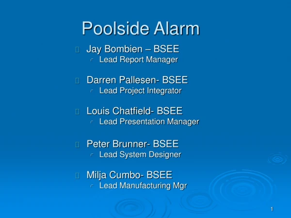
Poolside Alarm. Jay Bombien – BSEE Lead Report Manager Darren Pallesen- BSEE Lead Project Integrator Louis Chatfield- BSEE Lead Presentation Manager Peter Brunner- BSEE Lead System Designer Milja Cumbo- BSEE Lead Manufacturing Mgr. Major Functions and Features. Functions:

E N D
Poolside Alarm • Jay Bombien – BSEE • Lead Report Manager • Darren Pallesen- BSEE • Lead Project Integrator • Louis Chatfield- BSEE • Lead Presentation Manager • Peter Brunner- BSEE • Lead System Designer • Milja Cumbo- BSEE • Lead Manufacturing Mgr
Major Functions and Features • Functions: • Monitor a pool for potential hazardous situations • Loud audible alarms when a child falls in unnoticeably • Features: • Outdoor unit will display water temp, air temp, and low battery indicator • Solar cells on poolside unit to keep outdoor battery charged • User Control On/Off
Poolside Alarm • The device will monitor a pool for potential hazardous situations. (i.e. child falling in) • Indoor unit will display water temp, air temp, and low battery indicator. • Wireless home receiver and display unit with loud audible signal. • Solar cells on poolside unit to keep outdoor battery charged.
Poolside Alarm Similar Existing Product
Poolside Alarm Block Assignment Louis Peter Jay Darren Milja Outdoor Indoor Power Supply Power Supply Air / Water Sensor Alarm RF Transceiver Wave Sensor Indoor MPU and Display Motion Sensor Data Lines Power Lines Alarm
Standard Requirements System Standard Requirements: Market: • Est. Total Market Size $1,000,000 • Est. Annual Vol. 3,000 • Min. List Price $250 Manufacturing: • Min. Total Parts Count 160 • Max. Unique Parts Count 50 • Max. Parts & Materials Cost $175 • Max. MFG Assembly / Test Cost $50 Life Cycle: • Est. Max. Production Lifetime 10 years • Product Life Reliability in MTBF 1.99 years • Full Warranty Period 30 days
Standard Requirements Power Sources Indoor: • Source(1): 120Vac 108V to 138V Frequency Range: 57-63Hz AC Power Dissipation: 400 mW Plugs: Type B (Flat blades with round grounding pin) 2.1 mm male-to-female DC Plug • Source(2): 3AA 3.9V to 4.8V • Battery Power: 2000 mAh Outdoor: • Source(1): Solar Cell 13.3V to 16.2V • Source(2): 8AA 10.8V to 12.6V • Battery Power 2000 mAh Max. Total Power 20W
Performance Requirements Mechanical: • Max. Product Vol. 11,000 • Max. Shipping Container Vol. 8,000 • Max. Product Mass 5 kg • Max. # of boards 3 • Max. Total PCB Area 425 cm2 • Max. Shock Force • Indoor 50 G’s • Outdoor 10 G’s • Max. Shock Repetitions / Year 15 Environmental: • Operating Ambient Temp. Range 5°C to 50° • Operating Ambient Humidity Range 0%Rh to 100%Rh • Operating Altitude Range 0.5 to 1.5 ATM • Storage Ambient Temp. Range -20°C to 80°C • Storage Ambient Humidity Range 0%Rh to 100%Rh • Storage / Shipping Altitude Range -100m to 3000m • Max Storage Duration 3 years
Safety Standards • UL 464 - Audible Signal Appliances • Electrically and electronically operated bells, buzzers, horns, and similar audible signal appliances intended for indoor or outdoor locations. • UL 1703 - Flat-Plate Photovoltaic Modules and Panels • Flat-plate photovoltaic modules used as either freestanding or attached to buildings • PS 128-01, Provisional Specification for Pool Alarms • Alarms sound at poolside and in adjacent buildings when a minimum weight of 18 lbs hits the water. • Alarms sound at poolside and in adjacent buildings that a minimum sound of 80dB at 100ft is possible • IEC 61558-1 • Safety of power transformers, power supply units and similar devices
Key Risk Areas • Developing and implementing a wave sensor could be very complicated • Not much market on workable child safety poolside devices • Difficulty to present prototype. • Sensor Interfacing • Power Supply interfacing with step-down transformer • Outdoor product requiring waterproofing • Needs to be near foolproof, should not go off with falling branches, excessive wind, etc.
EMC Standard Summary Table US/FCC: 47 CFR 15 - Radio Frequency Devices 47 CFR 18 - Industrial Scientific and Medical Equipment 61000-3-3 EMC Part 3: Limits - Section 3: low-voltage supplies <16A 61000-4-2 EMC Part 4: Test/measurement techniques - Section 2: ESD immunity tests 61000-4-3 EMC Part 4: Test/measurement techniques - Section 3: Radiated radiofrequency immunity 61000-4-6 EMC Part 4: Test/measurement techniques - Section 6: Conducted radiofrequency immunity 61000-4-11 EMC Part 4: Test/measurement techniques - Section 11: Voltage dips, short interruptions and variations CISPR:11 Limits and methods of measurement for Industrial, Scientific and Medical Equipment 16 Specifications for Radio Interference Measuring Apparatus and Measurement Methods 22 Limits and Methods of Measurements of Radio Interference of Information Equipment
Design Plan Summary Total Manpower Estimated: 1750 hrs Available: 975 hrs Total Material Cost Estimated: $337 Available: $350 Percentage of total manpower System Design Tasks: 15% Detailed Design Tasks: 35% Verification Tasks: 15% Documentation Tasks: 35%
Prototype Summary Slide • Total # of bds • 8 bds – 1 for Each Block • Total PCB area (cm2) • B1(40), B2(65), B3(40), B4(50), B5(50), B6(40), B7(50), B8(90) • Total = 425 • Technology: • Perfboard, PCB, Breadboard • Soldering & Wirewrap
Outdoor Power Supply Peter Brunner
Poolside Alarm Block Assignment Peter Outdoor Indoor Power Supply Power Supply Alarm Air / Water Sensor RF Transceiver Wave Sensor Indoor MPU and Display Motion Sensor Data Lines Power Lines Alarm
Functional Purpose • To receive Infra red rays from the sun to charge the solar panels • To recharge the battery through a regulator when it loses 10% of its power. • To output the required regulated voltage for the other block power inputs
Performance Requirements Electrical Interfaces: • Signal Type: Power. • Power Consumption: 2W • Signal Direction: Input / Output. • Battery Type: 8AA • Output Voltage: • Nominal: 3.3 Range: 3-3.6 • Nominal: 12 Range: 10.8-13.2 • Nominal: 9 Range: 8.1-9.9 • Output Current max. : 1 A • Input Voltage: • Nominal: 15.4 Range: 13.3 – 16.4 • Input Current max: 120 mA Safety Standard: • UL 1703 - Flat-Plate Photovoltaic Modules and Panels EMC Standard: • EMC 61000-3-3: Limitation of voltage fluctuations and flicker in low-voltage supplies <16A
Mechanical Block cost <$65 Parts count <15 Unique parts count <6 PCB Area 40 cm2 Environment: Operating temperature range 5 to 55 C Storage temperature range -20C to 65C Operating humidity 0 to 100% Life Cycle Reliability MTBF 237.3 years R(1 warranty) 99.7% Disposal Throw away Percent Allocations 26% of cost 10% of parts 9% of PCB area Standard Requirements
Block Assignment Sun 15.4V 12V Charging Circuit Battery Switching Regulator 3.3V 9V Other Blocks
Parts Count Reliability • Total Fits = 480.77, Total MTBF (yrs) = 237.3 • R(30 day warranty) = e^(-0.8/237.3) * 100% = 99.7% • Dominant Failure part is the Flexible Solar Panel. Not much can be done to improve this part for higher reliability.
Indoor Power Supply Jay Bombien
Poolside Alarm Block Assignment Jay Outdoor Indoor Power Supply Power Supply Alarm Air / Water Sensor RF Transceiver Wave Sensor Indoor MPU and Display Motion Sensor Data Lines Power Lines Alarm
Indoor Power Supply Block Description and Purpose: • Electrical device that will transform the standard wall electricity (AC) to lower voltages (DC). • The DC voltage will power the indoor control panel, RF transceiver, and the alarm. • Will charge the battery unit used as the backup power system.
Block cost <$25 Parts count <18 Unique parts count <8 PCB Area 65 cm2 Power consumption 3 W Operating temperature range 5 to 55 C Storage temperature range -20C to 65C Reliability MTBF 7.8 years Operating humidity 0 to 100% Disposal Throw away Percent Allocation: Cost: 10.0% Parts: 11.25% PCB: 15.29% Indoor Power Supply Standard Requirements
Indoor Power Supply Performance Requirements * Electrical Interfaces: • Signal Type:Power • Signal Direction: Input / Output. • Output Voltage: Nominal: 3.3 VDC (Range: 3.0 – 3.6 VDC) • V-Ripple max. :100 mV • Output Current max. : 1 A • Input Voltage: Nominal: 120 VAC (Range:108 - 138 VAC) • Input Current max:1.038 A Safety Standard: • IEC 61558-1: Safety of power transformers, power supply units and similar devices EMC Standard: EMC Standard: • EMC 61000-3-3: Limitation of voltage fluctuations and flicker in low- voltage supplies <16A
Indoor Power Supply AC/DC Converter Block DC Regulator Circuit Battery Charger Circuit Converter/Charger Switch Alarm Battery DC Regulator Circuit Indoor MPU and Display
Indoor Power Supply Signal Input/Output Summary
Indoor Power Supply Prototyping Plan
Indoor Power Supply Block Parts Count Reliability • Total FITs: 14620 Total MTBF (years): 7.8 • The MOS Digital ICs are most unreliable • R = 90.25%
Indoor MPU and Display Darren Pallesen
Poolside Alarm Block Assignment Darren Outdoor Indoor Power Supply Power Supply Alarm Air / Water Sensor RF Transceiver Wave Sensor Indoor MPU and Display Motion Sensor Data Lines Power Lines Alarm
Indoor MPU and DisplayBlock Description • Allows user to turn the unit on/off. Also allows user to deactivate both alarms from inside. • Receives signals from the transceiver (alarm activated, alarm deactivated from outside, outdoor unit power off, and low battery). • Transfers signals to alarm (activate/deactivate). • Sends signals to the indoor display unit for user visibility (power on, low battery, alarm activated).
Indoor MPU and DisplayPerformance Requirements User Indicators and Displays: • Indicator Parameters: Power On, Outdoor Unit Power Off, Low Battery, Alarm Activated. • Indicator Color and Type: Amber LED, Green LED, Green LED, Red LEDs. • Indicator Viewing Environment: Indoor Lighting, Complete Darkness. Electrical Interfaces: • Power Consumption: 1 W • Signal Types: DC Power, Digital. • Signal Directions: Input, Bi-Directional, Output. • Input Nominal Voltage: 3.3 VDC Range: 3.0 VDC – 3.3 VDC • Input Current Max: 24 mA • Output Nominal Voltage: 3.3 VDC Range: 3.0 VDC – 3.3 VDC • Output Current Max: 24 mA EMC Standard: • 61000-4-2 EMC Part 4: Test/measurement techniques - Section 2: ESD immunity tests
Mechanical: Block Cost < $25 Parts Count < 16 Unique Parts Count < 5 PCB Area 40 cm2 Environmental: Operating temperature range 5 to 55 C Storage temperature range -20C to 65C Operating humidity 0 to 100% Life Cycle: MTBF(years) 183.53 years R(warranty) 99.57% Disposal Throw away Percent Allocation: Block Cost 10% of Total Parts Count 10% of Total PCB Area 9% of Total Indoor MPU and DisplayStandard Requirements
Indoor MPU and DisplayBlock Detail Alarm Turn-Off User Control Power Supply Power On / Off 3.3V Alarm Activated MPU RF Transceiver Alarm Turn-Off Alarm On / Off Low Battery Alarm Outdoor Unit Power Off Alarm Turn-Off Outdoor Unit Off Digital Signals Low Battery Alarm Activated Power On Analog Signals Display (LED Indicators)
Indoor MPU and DisplayParts Count Reliability Estimation • MTBF(years) = 183.53 • R(30 day warranty) = e^-(0.8 / 183.53) = 0.9957 = 99.57% • The dominant part for unreliability is the CPLD chip. Not much can be done to improve the reliability of this part because of the amount of gates in the IC.
Wave Sensor Jay Bombien
Poolside Alarm Block Assignment Jay Outdoor Indoor Power Supply Power Supply Alarm Air / Water Sensor RF Transceiver Wave Sensor Indoor MPU and Display Motion Sensor Data Lines Power Lines Alarm
Wave Sensor Block Description and Purpose: • Sensing unit that will detect the presence of wave motion in the pool. • This signal will be passed through an A/D converter and then on to the RF transceiver.
Block cost <$20 Parts count <12 Unique parts count <2 PCB Area 30 cm2 Power consumption <2.25 W Operating temperature range 5 to 55 C Storage temperature range -20C to 65C Reliability MTBF 9.9 years Operating humidity 0 to 100% Disposal Throw away Percent Allocation: Cost: 8.0% Parts: 7.5% PCB: 7.05% Wave Sensor Standard Requirements
Wave Sensor Performance Requirements * Electrical Interface: • Signal Type: Power. • Signal Direction: Input • Input Nominal Voltage: 9 VDC (Range: 8.1 – 9.9 VDC) • Input Current max: 0.5 A * Data Interface: • Signal Type: Digital • Signal Direction: Output • Input Nominal Voltage: 1.4 VDC (Range: 0.8 – 2.0 VDC) • Input Current max: 5 uA EMC Standard: • 61000-3-3 EMC Part 3: Limits - Section 3: Limitation of voltage fluctuations and flicker in low-voltage supplies <16A • 61000-4-11 EMC Part 4: Test/measurement techniques - Section 11: Voltage dips, short interruptions and variations
Wave Sensor Outdoor Power Supply Oscillator Circuit Voltage Comparator RF Transceiver Wave Sensing Unit Data Lines Power Lines
Wave Sensor Signal Input/Output Summary
Wave Sensor Prototyping Plan
Wave Sensor Block Parts Count Reliability • Total FITs: 11577 Total MTBF (years): 9.9 • The MOS Digital ICs are most unreliable • R = 92.24%